Skip to content

ROCKPro64 - RP64.GPIO

Angeheftet Verschoben Hardware
  • Heute mal eine Bastelstunde und direkt vorne weg eine dicke fette Warnung!

    Hiermit kann man seinen ROCKPro64 in Elektroschrott verwandeln! Ich hafte nicht für Schäden! Hirn einschalten vorher! 😉

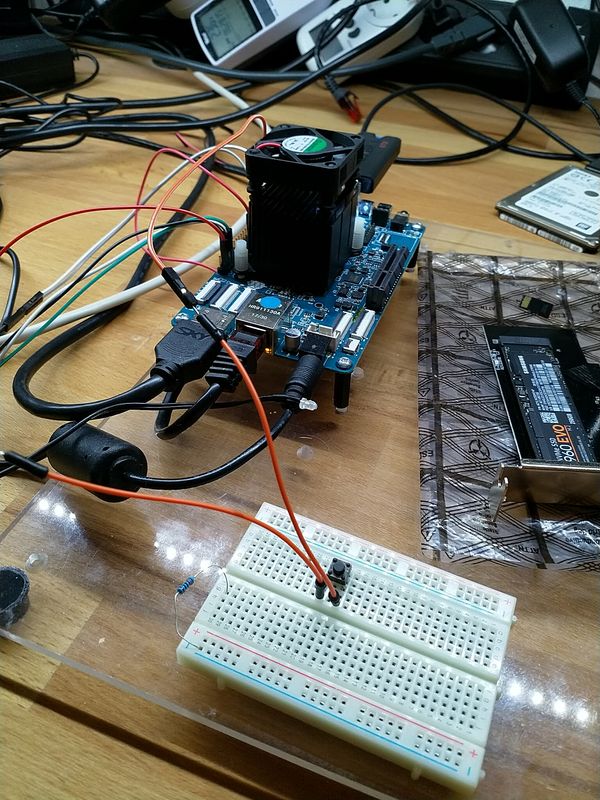
    0_1537440456037_IMG_20180920_124609_ergebnis.jpg

    Für den Rock64 gibt es ein Projekt das die RPi.GPIO cloned. https://github.com/Leapo/Rock64-R64.GPIO

    A Python GPIO library for the Rock64 single-board computer (RPi.GPIO clone).

    GPIO - was ist das? Wiki

    Gut, damit läuft das aber nicht auf einem ROCKPro64, weil die Nummerierungen der Pins nicht passen. Aber dafür gibt es da draußen Leute, die sich solche Themen erarbeiten.

    Quelle: https://forum.pine64.org/showthread.php?tid=6419&pid=40185#pid40185

    Erstmal das Ergebnis 🙂

    Output Test R64.GPIO Module...
    This channel (ROCK 52) is already in use, continuing anyway.  Use GPIO.setwarnings(False) to disable warnings.
    
    Testing GPIO Input/Output:
    Output State ELSE: 1
    Output State IF : 0
    Output State ELSE: 1
    Output State IF : 0
    Output State ELSE: 1
    Output State IF : 0
    Output State ELSE: 1
    Output State IF : 0
    Output State ELSE: 1
    Output State IF : 0
    Output State ELSE: 1
    

    Video

    So, nun das Ganze mal von vorne.

    Software

    Wir brauchen Python

    sudo apt-get install python
    

    Danach laden wir das Projekt

    git clone https://github.com/Leapo/Rock64-R64.GPIO
    

    Wie oben schon geschrieben, passen die Pin Nummern nicht.

    cd Rock64-R64.GPIO/R64
    nano _GPIO.py
    

    In dieser Datei ergänzen wir wie folgt.

    # Define GPIO arrays
    #ROCK_valid_channels = [27, 32, 33, 34, 35, 36, 37, 38, 64, 65, 67, 68, 69, 76, 79, 80, 81, 82, 83, 84, 85, 86, 87, 88, 89, 96, 97, 98, 100, 101, 102, 103, 104]
    #BOARD_to_ROCK = [0, 0, 0, 89, 0, 88, 0, 0, 64, 0, 65, 0, 67, 0, 0, 100, 101, 0, 102, 97, 0, 98, 103, 96, 104, 0, 76, 68, 69, 0, 0, 0, 38, 32, 0, 33, 37, 34, 36, 0, 35, 0, 0, 81, 82, 87, 83, 0, 0, 80, 79, 85, 84, 27, 86, 0, 0, 0, 0, 0, 0, 89, 88]
    #BCM_to_ROCK = [68, 69, 89, 88, 81, 87, 83, 76, 104, 98, 97, 96, 38, 32, 64, 65, 37, 80, 67, 33, 36, 35, 100, 101, 102, 103, 34, 82]
    ROCK_valid_channels = [52,53,152,54,50,33,48,39,41,43,155,156,125,122,121,148,147,120,36,149,153,42,45,44,124,126,123,127]
    BOARD_to_ROCK = [0,0,0,52,0,53,0,152,148,0,147,54,120,50,0,33,36,0,149,48,0,39,153,41,42,0,45,43,44,155,0,156,124,125,0,122,126,121,123,0,127]
    BCM_to_ROCK = [43,44,52,53,152,155,156,45,42,39,48,41,124,125,148,147,124,54,120,122,123,127,33,36,149,153,121,50] 
    

    Das Ganze dann abspeichern.

    Im Pfad rock64@rockpro64v_2_1:~/Rock64-R64.GPIO$ eine Datei anlegen test.py

    #!/usr/bin/env python
    
    # Frank Mankel, 2018, LGPLv3 License
    # Rock 64 GPIO Library for Python
    # Thanks Allison! Thanks smartdave!
    
    import R64.GPIO as GPIO
    from time import sleep
    
    print("Output Test R64.GPIO Module...")
    
    # Set Variables
    var_gpio_out = 52
    #var_gpio_in = 18
    
    
    # GPIO Setup
    GPIO.setwarnings(True)
    GPIO.setmode(GPIO.ROCK)
    GPIO.setup(var_gpio_out, GPIO.OUT, initial=GPIO.HIGH)       # Set up GPIO as an output, with an initial state of HIGH
    #GPIO.setup(var_gpio_in, GPIO.IN, pull_up_down=GPIO.PUD_UP)  # Set up GPIO as an input, pullup enabled
    
    # Test Output
    print("")
    print("Testing GPIO Input/Output:")
    
    while True:
            var_gpio_state = GPIO.input(var_gpio_out)       # Return State of GPIO
            if var_gpio_state == str(0):
                    GPIO.output(var_gpio_out,1)                         # Set GPIO to LOW
                    print("Output State IF : " + str(var_gpio_state))              # Print results
            else:
                    GPIO.output(var_gpio_out,0)                         # Set GPIO to LOW
                    print("Output State ELSE: " + str(var_gpio_state))
            sleep(0.5)
    exit()
    

    Was fehlt noch? Der Anschluß der LED. In meinem Beispiel ist die LED wie folgt angeschlossen.

    • Plus(+) der LED an PIN 3 (GPIO1_C4)
    • Minus(-)- der LED an Pin 39 (GND)

    Zum korrekten Anschließen der LED empfehle ich die Lektüre dieses Beitrages!


    Starten des Scriptes

    Um das Script zu starten benutzt man

    sudo python test.py
    

    Ohne sudo bekam ich Fehlermeldungen.


    Fazit

    Es gibt da für mich einige Unbekannte bei dem Thema. Das wären

    • Stimmt die Nummerierung, ist sie komplett?
    • GPIO.setmode(GPIO.ROCK) ermöglichte mir dann mit 52 endlich was zu finden?

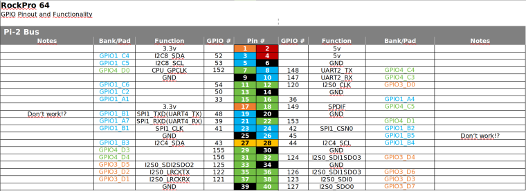
    Wir brauchen eine vernünftige Auflistung der Nummern zu den PINs. Gibt es das ? Stimmen alle PIN-Nummern!?

    Bitte dran denken, da kann man sich evt. den ROCKPro64 mit schrotten! Also schön vorsichtig!!

    Danke an Allison und smartdave für die Arbeit!

    Ach, fast vergessen. Ich hab von Python recht wenig Ahnung, macht aber Spaß weil man unkompliziert und schnell zu Ergebnissen kommt.

  • 0_1537460597625_ROCKPro64_GPIO_Reference.png

  • Hiermit kann man seinen ROCKPro64 in Elektroschrott verwandeln! Ich hafte nicht für Schäden! Hirn einschalten vorher! 😉
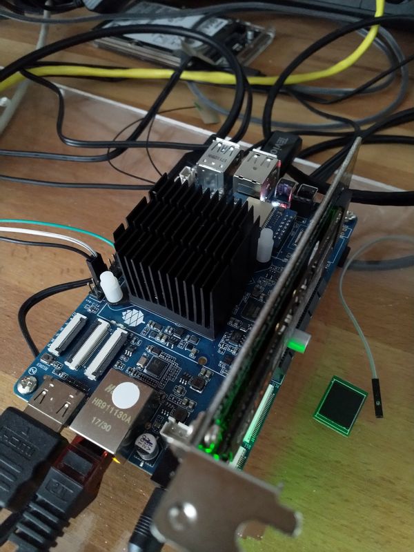
    Ich bin Euch noch was schuldig geblieben. Nur Ausgänge steuern ist blöd, man braucht auch Eingänge 🙂

    0_1537522069566_Input_ergebnis.jpg

    Beispiel

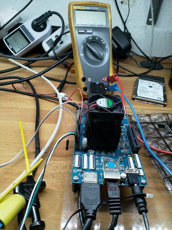
    Wenn der Taster im Bild betätigt wird, soll die LED blinken.

    Script

    Wir benutzen folgende Ein- Augänge des ROCKPro64.

     # Set Variables
     var_gpio_out = 156
     var_gpio_in = 155
    

    Das heißt:

    • an Pin 1 (3,3V) kommt eine Strippe des Tasters
    • an Pin 29 (Input) kommt eine Strippe des Tasters
    • an Pin 31 (Putput) kommt der Plus-Pol der LED
    • an Pin 39 (GND) kommt der Minus-Pol der LED

    Somit wird auf den Eingang (Pin 29) bei Betätigung des Tasters 3,3 Volt angelegt. Damit wird dann der Eingang als High (1) erkannt. Die LED wird über den Ausgang (Pin 31) gesteuert.

    #!/usr/bin/env python
    
    # Frank Mankel, 2018, LGPLv3 License
    # Rock 64 GPIO Library for Python
    # Thanks Allison! Thanks smartdave!
    
    import R64.GPIO as GPIO
    from time import sleep
    
    print("Output Test R64.GPIO Module...")
    
    # Set Variables
    var_gpio_out = 156
    var_gpio_in = 155
    
    
    # GPIO Setup
    GPIO.setwarnings(True)
    GPIO.setmode(GPIO.ROCK)
    GPIO.setup(var_gpio_out, GPIO.OUT, initial=GPIO.HIGH)       # Set up GPIO as an output, with an initial state of HIGH
    GPIO.setup(var_gpio_in, GPIO.IN, pull_up_down=GPIO.PUD_UP)  # Set up GPIO as an input, pullup enabled
    
    # Test Output
    print("")
    print("Testing GPIO Input/Output:")
    
    
    while True:
            var_gpio_state_in = GPIO.input(var_gpio_in)
            var_gpio_state = GPIO.input(var_gpio_out)                       # Return State of GPIO
            if var_gpio_state == str(0) and var_gpio_state_in == str(1):
                    GPIO.output(var_gpio_out,1)                             # Set GPIO to HIGH
                    print("Input State: " + str(var_gpio_state_in))         # Print results
                    print("Output State IF : " + str(var_gpio_state))       # Print results
            else:
                    GPIO.output(var_gpio_out,0)                             # Set GPIO to LOW
                    print("Input State: " + str(var_gpio_state_in))         # Print results
                    print("Output State ELSE: " + str(var_gpio_state))      # Print results
            sleep(0.5)
    exit()
    
  • Das Projekt (ein Fork) ist aktualisiert und kann jetzt für den ROCK64 und den ROCKPro64 benutzt werden.

    Mit

    setrock('ROCKPRO64')
    

    kann man das Script für den ROCKPro64 anpassen.

    Quelle: https://forum.pine64.org/showthread.php?tid=6419&pid=41270#pid41270

    Sobald ich mal Zeit und Lust habe, werde ich das Testen und hier berichten.

  • Die Coderin von dieser Library Leapo schreibt folgendes

    For anyone using my GPIO library: Just fixed a pretty major bug with GPIO.input, where it would return "1" or "0" as a string rather than as an integer. This fix greatly improves compatibility with scripts written originally for RPI.GPIO. Edit: I've also also fixed Python 3 compatibility (library would crash-out under python 3 if certain debug text was called for).

    Quelle: discordapp.com

    Für den ein oder anderen, der das nutzt vermutlich sehr interessant.

  • Hallo zusammen,

    da ich weiß das dieser Artikel recht beliebt ist, wollen wir den heute mal aktualisieren. Vieles aus den vorherigen Beiträgen passt noch. Es gibt aber kleine Anpassungen.

    Hardware

    • ROCKPro64v21. 2GB RAM

    Software

    • Kamils Release 0.10.9
    • Linux rockpro64 5.6.0-1132-ayufan-g81043e6e109a #ayufan SMP Tue Apr 7 10:07:35 UTC 2020 aarch64 GNU/Linux

    Installation

     apt install python
    

    Danach laden wir das Projekt

    git clone https://github.com/Leapo/Rock64-R64.GPIO
    

    PIN Nummern anpassen

    cd Rock64-R64.GPIO/R64
    nano _GPIO.py
    

    Datei ergänzen

    # Define GPIO arrays
    #ROCK_valid_channels = [27, 32, 33, 34, 35, 36, 37, 38, 64, 65, 67, 68, 69, 76, 79, 80, 81, 82, 83, 84, 85, 86, 87, 88, 89, 96, 97, 98, 100, 101, 102, 103, 104]
    #BOARD_to_ROCK = [0, 0, 0, 89, 0, 88, 0, 0, 64, 0, 65, 0, 67, 0, 0, 100, 101, 0, 102, 97, 0, 98, 103, 96, 104, 0, 76, 68, 69, 0, 0, 0, 38, 32, 0, 33, 37, 34, 36, 0, 35, 0, 0, 81, 82, 87, 83, 0, 0, 80, 79, 85, 84, 27, 86, 0, 0, 0, 0, 0, 0, 89, 88]
    #BCM_to_ROCK = [68, 69, 89, 88, 81, 87, 83, 76, 104, 98, 97, 96, 38, 32, 64, 65, 37, 80, 67, 33, 36, 35, 100, 101, 102, 103, 34, 82]
    ROCK_valid_channels = [52,53,152,54,50,33,48,39,41,43,155,156,125,122,121,148,147,120,36,149,153,42,45,44,124,126,123,127]
    BOARD_to_ROCK = [0,0,0,52,0,53,0,152,148,0,147,54,120,50,0,33,36,0,149,48,0,39,153,41,42,0,45,43,44,155,0,156,124,125,0,122,126,121,123,0,127]
    BCM_to_ROCK = [43,44,52,53,152,155,156,45,42,39,48,41,124,125,148,147,124,54,120,122,123,127,33,36,149,153,121,50] 
    

    Abspeichern.

    Datei test.py anlegen

    nano test.py
    

    Inhalt

    #!/usr/bin/env python
    
    # Frank Mankel, 2018, LGPLv3 License
    # Rock 64 GPIO Library for Python
    # Thanks Allison! Thanks smartdave!
    
    import R64.GPIO as GPIO
    from time import sleep
    
    print("Output Test R64.GPIO Module...")
    
    # Set Variables
    var_gpio_out = 156
    var_gpio_in = 155
    
    
    # GPIO Setup
    GPIO.setwarnings(True)
    GPIO.setmode(GPIO.ROCK)
    GPIO.setup(var_gpio_out, GPIO.OUT, initial=GPIO.HIGH)       # Set up GPIO as an output, with an initial state of HIGH
    GPIO.setup(var_gpio_in, GPIO.IN, pull_up_down=GPIO.PUD_UP)  # Set up GPIO as an input, pullup enabled
    
    # Test Output
    print("")
    print("Testing GPIO Input/Output:")
    
    
    while True:
            var_gpio_state_in = GPIO.input(var_gpio_in)
            var_gpio_state = GPIO.input(var_gpio_out)                       # Return State of GPIO
            if var_gpio_state == 0 and var_gpio_state_in == 1:
                    GPIO.output(var_gpio_out,GPIO.HIGH)                             # Set GPIO to HIGH
                    print("Input State: " + str(var_gpio_state_in))         # Print results
                    print("Output State IF : " + str(var_gpio_state))       # Print results
            else:
                    GPIO.output(var_gpio_out,GPIO.LOW)                             # Set GPIO to LOW
                    print("Input State: " + str(var_gpio_state_in))         # Print results
                    print("Output State ELSE: " + str(var_gpio_state))      # Print results
            sleep(0.5)
    exit()
    

    Beispiel

    Bild Text

    Wenn der Taster im Bild betätigt wird, soll die LED blinken.

    Wir benutzen folgende Ein- Augänge des ROCKPro64.

    # Set Variables
    var_gpio_out = 156
    var_gpio_in = 155
    

    Das heißt:

    • an Pin 1 (3,3V) kommt eine Strippe des Tasters
    • an Pin 29 (Input) kommt eine Strippe des Tasters
    • an Pin 31 (Output) kommt der Plus-Pol der LED
    • an Pin 39 (GND) kommt der Minus-Pol der LED

    Somit wird auf den Eingang (Pin 29) bei Betätigung des Tasters 3,3 Volt angelegt. Damit wird dann der Eingang als High (1) erkannt. Die LED wird über den Ausgang (Pin 31) gesteuert.

    Starten kann man das Script mit

    python test.py
    

  • ROCKPro64 - Eine Einführung für Einsteiger

    Verschoben ROCKPro64
    1
    0 Stimmen
    1 Beiträge
    480 Aufrufe
    Niemand hat geantwortet
  • ROCKPro64 - LAN Schnittstelle

    Verschoben ROCKPro64
    1
    0 Stimmen
    1 Beiträge
    380 Aufrufe
    Niemand hat geantwortet
  • Rock64 and RockPro64 ayufan’s packages

    Angeheftet ROCKPro64
    1
    0 Stimmen
    1 Beiträge
    880 Aufrufe
    Niemand hat geantwortet
  • USB-Adapter für eMMC-Modul

    Hardware
    1
    0 Stimmen
    1 Beiträge
    1k Aufrufe
    Niemand hat geantwortet
  • Eure Meinung zum ROCKPro64 ?

    ROCKPro64
    1
    0 Stimmen
    1 Beiträge
    579 Aufrufe
    Niemand hat geantwortet
  • IPFire auf dem ROCKPro64

    ROCKPro64
    2
    0 Stimmen
    2 Beiträge
    618 Aufrufe
    FrankMF

    Falls es jemanden da draußen interessiert, hier eine Liste der Dinge die funktionieren

    GREEN Die LAN-Schnittstelle wird einwandfrei erkannt Webserver läuft, Weboberfläche erreichbar

    Das war's dann mit den positiven Daten

    jede Menge Kernelfehler iptables Fehler Modul fehlt?? kein LAN-Adapter, WLan-Adapter wird erkannt Lizenzverbindungen lassen sich nicht bestätigen nach der Installation ist die Konsole weg usw. usf

    🙂

  • 960 EVO M.2 vs. 970 PRO M.2

    ROCKPro64
    2
    0 Stimmen
    2 Beiträge
    2k Aufrufe
    FrankMF

    Die 970 steckt jetzt in meinem Haupt-PC. Dort werkelt ein aktuelles Linux Mint Cinnamon 19. Zum Vergleich.

    100M frank@frank-MS-7A34:~$ sudo iozone -e -I -a -s 100M -r 4k -r 16k -r 512k -r 1024k -r 16384k -i 0 -i 1 -i 2 [sudo] Passwort für frank: Iozone: Performance Test of File I/O Version $Revision: 3.429 $ Compiled for 64 bit mode. Build: linux-AMD64 Contributors:William Norcott, Don Capps, Isom Crawford, Kirby Collins Al Slater, Scott Rhine, Mike Wisner, Ken Goss Steve Landherr, Brad Smith, Mark Kelly, Dr. Alain CYR, Randy Dunlap, Mark Montague, Dan Million, Gavin Brebner, Jean-Marc Zucconi, Jeff Blomberg, Benny Halevy, Dave Boone, Erik Habbinga, Kris Strecker, Walter Wong, Joshua Root, Fabrice Bacchella, Zhenghua Xue, Qin Li, Darren Sawyer, Vangel Bojaxhi, Ben England, Vikentsi Lapa. Run began: Sun Aug 19 16:52:19 2018 Include fsync in write timing O_DIRECT feature enabled Auto Mode File size set to 102400 kB Record Size 4 kB Record Size 16 kB Record Size 512 kB Record Size 1024 kB Record Size 16384 kB Command line used: iozone -e -I -a -s 100M -r 4k -r 16k -r 512k -r 1024k -r 16384k -i 0 -i 1 -i 2 Output is in kBytes/sec Time Resolution = 0.000001 seconds. Processor cache size set to 1024 kBytes. Processor cache line size set to 32 bytes. File stride size set to 17 * record size. random random bkwd record stride kB reclen write rewrite read reread read write read rewrite read fwrite frewrite fread freread 102400 4 92640 121912 131074 139525 45719 116653 102400 16 254286 285267 285539 320370 108049 314486 102400 512 537947 581765 606103 598137 537701 588214 102400 1024 566892 547921 567369 597286 518014 558686 102400 16384 1407884 1642148 1941120 2115608 2006947 1668118 iozone test complete. 1000M frank@frank-MS-7A34:~$ sudo iozone -e -I -a -s 1000M -r 4k -r 16k -r 512k -r 1024k -r 16384k -i 0 -i 1 -i 2 Iozone: Performance Test of File I/O Version $Revision: 3.429 $ Compiled for 64 bit mode. Build: linux-AMD64 Contributors:William Norcott, Don Capps, Isom Crawford, Kirby Collins Al Slater, Scott Rhine, Mike Wisner, Ken Goss Steve Landherr, Brad Smith, Mark Kelly, Dr. Alain CYR, Randy Dunlap, Mark Montague, Dan Million, Gavin Brebner, Jean-Marc Zucconi, Jeff Blomberg, Benny Halevy, Dave Boone, Erik Habbinga, Kris Strecker, Walter Wong, Joshua Root, Fabrice Bacchella, Zhenghua Xue, Qin Li, Darren Sawyer, Vangel Bojaxhi, Ben England, Vikentsi Lapa. Run began: Sun Aug 19 15:28:38 2018 Include fsync in write timing O_DIRECT feature enabled Auto Mode File size set to 1024000 kB Record Size 4 kB Record Size 16 kB Record Size 512 kB Record Size 1024 kB Record Size 16384 kB Command line used: iozone -e -I -a -s 1000M -r 4k -r 16k -r 512k -r 1024k -r 16384k -i 0 -i 1 -i 2 Output is in kBytes/sec Time Resolution = 0.000001 seconds. Processor cache size set to 1024 kBytes. Processor cache line size set to 32 bytes. File stride size set to 17 * record size. random random bkwd record stride kB reclen write rewrite read reread read write read rewrite read fwrite frewrite fread freread 1024000 4 95635 121379 108328 108265 45369 123356 1024000 16 239238 314359 245937 241877 105865 297193 1024000 512 596812 620661 442100 382367 351948 613525 1024000 1024 608903 611898 434687 417192 412018 646465 1024000 16384 1898738 2004622 2143647 2188062 2099674 1983240 iozone test complete.

    Da scheint auf dem ROCKPro64 noch ein wenig Luft nach oben.

  • stretch-minimal-rockpro64

    Verschoben Linux
    3
    0 Stimmen
    3 Beiträge
    1k Aufrufe
    FrankMF

    Mal ein Test was der Speicher so kann.

    rock64@rockpro64:~/tinymembench$ ./tinymembench tinymembench v0.4.9 (simple benchmark for memory throughput and latency) ========================================================================== == Memory bandwidth tests == == == == Note 1: 1MB = 1000000 bytes == == Note 2: Results for 'copy' tests show how many bytes can be == == copied per second (adding together read and writen == == bytes would have provided twice higher numbers) == == Note 3: 2-pass copy means that we are using a small temporary buffer == == to first fetch data into it, and only then write it to the == == destination (source -> L1 cache, L1 cache -> destination) == == Note 4: If sample standard deviation exceeds 0.1%, it is shown in == == brackets == ========================================================================== C copy backwards : 2812.7 MB/s C copy backwards (32 byte blocks) : 2811.9 MB/s C copy backwards (64 byte blocks) : 2632.8 MB/s C copy : 2667.2 MB/s C copy prefetched (32 bytes step) : 2633.5 MB/s C copy prefetched (64 bytes step) : 2640.8 MB/s C 2-pass copy : 2509.8 MB/s C 2-pass copy prefetched (32 bytes step) : 2431.6 MB/s C 2-pass copy prefetched (64 bytes step) : 2424.1 MB/s C fill : 4887.7 MB/s (0.5%) C fill (shuffle within 16 byte blocks) : 4883.0 MB/s C fill (shuffle within 32 byte blocks) : 4889.3 MB/s C fill (shuffle within 64 byte blocks) : 4889.2 MB/s --- standard memcpy : 2807.3 MB/s standard memset : 4890.4 MB/s (0.3%) --- NEON LDP/STP copy : 2803.7 MB/s NEON LDP/STP copy pldl2strm (32 bytes step) : 2802.1 MB/s NEON LDP/STP copy pldl2strm (64 bytes step) : 2800.7 MB/s NEON LDP/STP copy pldl1keep (32 bytes step) : 2745.5 MB/s NEON LDP/STP copy pldl1keep (64 bytes step) : 2745.8 MB/s NEON LD1/ST1 copy : 2801.9 MB/s NEON STP fill : 4888.9 MB/s (0.3%) NEON STNP fill : 4850.1 MB/s ARM LDP/STP copy : 2803.8 MB/s ARM STP fill : 4893.0 MB/s (0.5%) ARM STNP fill : 4851.7 MB/s ========================================================================== == Framebuffer read tests. == == == == Many ARM devices use a part of the system memory as the framebuffer, == == typically mapped as uncached but with write-combining enabled. == == Writes to such framebuffers are quite fast, but reads are much == == slower and very sensitive to the alignment and the selection of == == CPU instructions which are used for accessing memory. == == == == Many x86 systems allocate the framebuffer in the GPU memory, == == accessible for the CPU via a relatively slow PCI-E bus. Moreover, == == PCI-E is asymmetric and handles reads a lot worse than writes. == == == == If uncached framebuffer reads are reasonably fast (at least 100 MB/s == == or preferably >300 MB/s), then using the shadow framebuffer layer == == is not necessary in Xorg DDX drivers, resulting in a nice overall == == performance improvement. For example, the xf86-video-fbturbo DDX == == uses this trick. == ========================================================================== NEON LDP/STP copy (from framebuffer) : 602.5 MB/s NEON LDP/STP 2-pass copy (from framebuffer) : 551.6 MB/s NEON LD1/ST1 copy (from framebuffer) : 667.1 MB/s NEON LD1/ST1 2-pass copy (from framebuffer) : 605.6 MB/s ARM LDP/STP copy (from framebuffer) : 445.3 MB/s ARM LDP/STP 2-pass copy (from framebuffer) : 428.8 MB/s ========================================================================== == Memory latency test == == == == Average time is measured for random memory accesses in the buffers == == of different sizes. The larger is the buffer, the more significant == == are relative contributions of TLB, L1/L2 cache misses and SDRAM == == accesses. For extremely large buffer sizes we are expecting to see == == page table walk with several requests to SDRAM for almost every == == memory access (though 64MiB is not nearly large enough to experience == == this effect to its fullest). == == == == Note 1: All the numbers are representing extra time, which needs to == == be added to L1 cache latency. The cycle timings for L1 cache == == latency can be usually found in the processor documentation. == == Note 2: Dual random read means that we are simultaneously performing == == two independent memory accesses at a time. In the case if == == the memory subsystem can't handle multiple outstanding == == requests, dual random read has the same timings as two == == single reads performed one after another. == ========================================================================== block size : single random read / dual random read 1024 : 0.0 ns / 0.0 ns 2048 : 0.0 ns / 0.0 ns 4096 : 0.0 ns / 0.0 ns 8192 : 0.0 ns / 0.0 ns 16384 : 0.0 ns / 0.0 ns 32768 : 0.0 ns / 0.0 ns 65536 : 4.5 ns / 7.2 ns 131072 : 6.8 ns / 9.7 ns 262144 : 9.8 ns / 12.8 ns 524288 : 11.4 ns / 14.7 ns 1048576 : 16.0 ns / 22.6 ns 2097152 : 114.0 ns / 175.3 ns 4194304 : 161.7 ns / 219.9 ns 8388608 : 190.7 ns / 241.5 ns 16777216 : 205.3 ns / 250.5 ns 33554432 : 212.9 ns / 255.5 ns 67108864 : 222.3 ns / 271.1 ns