ROCKPro64 - RP64.GPIO
-
Heute mal eine Bastelstunde und direkt vorne weg eine dicke fette Warnung!
Hiermit kann man seinen ROCKPro64 in Elektroschrott verwandeln! Ich hafte nicht für Schäden! Hirn einschalten vorher!
")
Für den Rock64 gibt es ein Projekt das die RPi.GPIO cloned. https://github.com/Leapo/Rock64-R64.GPIO
A Python GPIO library for the Rock64 single-board computer (RPi.GPIO clone).
GPIO - was ist das? Wiki
Gut, damit läuft das aber nicht auf einem ROCKPro64, weil die Nummerierungen der Pins nicht passen. Aber dafür gibt es da draußen Leute, die sich solche Themen erarbeiten.
Quelle: https://forum.pine64.org/showthread.php?tid=6419&pid=40185#pid40185
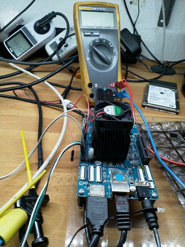
Erstmal das Ergebnis
")
Output Test R64.GPIO Module...
This channel (ROCK 52) is already in use, continuing anyway.  Use GPIO.setwarnings(False) to disable warnings.

Testing GPIO Input/Output:
Output State ELSE: 1
Output State IF : 0
Output State ELSE: 1
Output State IF : 0
Output State ELSE: 1
Output State IF : 0
Output State ELSE: 1
Output State IF : 0
Output State ELSE: 1
Output State IF : 0
Output State ELSE: 1
Video
So, nun das Ganze mal von vorne.
Software
Wir brauchen Python
sudo apt-get install pythonDanach laden wir das Projekt
git clone https://github.com/Leapo/Rock64-R64.GPIOWie oben schon geschrieben, passen die Pin Nummern nicht.
cd Rock64-R64.GPIO/R64
nano _GPIO.py
In dieser Datei ergänzen wir wie folgt.
# Define GPIO arrays
#ROCK_valid_channels = [27, 32, 33, 34, 35, 36, 37, 38, 64, 65, 67, 68, 69, 76, 79, 80, 81, 82, 83, 84, 85, 86, 87, 88, 89, 96, 97, 98, 100, 101, 102, 103, 104]
#BOARD_to_ROCK = [0, 0, 0, 89, 0, 88, 0, 0, 64, 0, 65, 0, 67, 0, 0, 100, 101, 0, 102, 97, 0, 98, 103, 96, 104, 0, 76, 68, 69, 0, 0, 0, 38, 32, 0, 33, 37, 34, 36, 0, 35, 0, 0, 81, 82, 87, 83, 0, 0, 80, 79, 85, 84, 27, 86, 0, 0, 0, 0, 0, 0, 89, 88]
#BCM_to_ROCK = [68, 69, 89, 88, 81, 87, 83, 76, 104, 98, 97, 96, 38, 32, 64, 65, 37, 80, 67, 33, 36, 35, 100, 101, 102, 103, 34, 82]
ROCK_valid_channels = [52,53,152,54,50,33,48,39,41,43,155,156,125,122,121,148,147,120,36,149,153,42,45,44,124,126,123,127]
BOARD_to_ROCK = [0,0,0,52,0,53,0,152,148,0,147,54,120,50,0,33,36,0,149,48,0,39,153,41,42,0,45,43,44,155,0,156,124,125,0,122,126,121,123,0,127]
BCM_to_ROCK = [43,44,52,53,152,155,156,45,42,39,48,41,124,125,148,147,124,54,120,122,123,127,33,36,149,153,121,50]
Das Ganze dann abspeichern.
Im Pfad rock64@rockpro64v_2_1:~/Rock64-R64.GPIO$ eine Datei anlegen test.py
#!/usr/bin/env python

# Frank Mankel, 2018, LGPLv3 License
# Rock 64 GPIO Library for Python
# Thanks Allison! Thanks smartdave!

import R64.GPIO as GPIO
from time import sleep

print("Output Test R64.GPIO Module...")

# Set Variables
var_gpio_out = 52
#var_gpio_in = 18


# GPIO Setup
GPIO.setwarnings(True)
GPIO.setmode(GPIO.ROCK)
GPIO.setup(var_gpio_out, GPIO.OUT, initial=GPIO.HIGH)       # Set up GPIO as an output, with an initial state of HIGH
#GPIO.setup(var_gpio_in, GPIO.IN, pull_up_down=GPIO.PUD_UP)  # Set up GPIO as an input, pullup enabled

# Test Output
print("")
print("Testing GPIO Input/Output:")

while True:
        var_gpio_state = GPIO.input(var_gpio_out)       # Return State of GPIO
        if var_gpio_state == str(0):
                GPIO.output(var_gpio_out,1)                         # Set GPIO to LOW
                print("Output State IF : " + str(var_gpio_state))              # Print results
        else:
                GPIO.output(var_gpio_out,0)                         # Set GPIO to LOW
                print("Output State ELSE: " + str(var_gpio_state))
        sleep(0.5)
exit()
Was fehlt noch? Der Anschluß der LED. In meinem Beispiel ist die LED wie folgt angeschlossen.
- Plus(+) der LED an PIN 3 (GPIO1_C4)
- Minus(-)- der LED an Pin 39 (GND)
Zum korrekten Anschließen der LED empfehle ich die Lektüre dieses Beitrages!
Starten des Scriptes
Um das Script zu starten benutzt man
sudo python test.pyOhne sudo bekam ich Fehlermeldungen.
Fazit
Es gibt da für mich einige Unbekannte bei dem Thema. Das wären
- Stimmt die Nummerierung, ist sie komplett?
- GPIO.setmode(GPIO.ROCK) ermöglichte mir dann mit 52 endlich was zu finden?
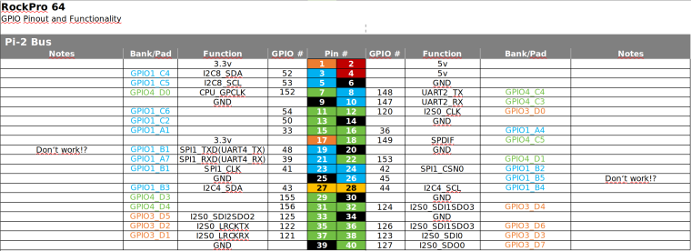
Wir brauchen eine vernünftige Auflistung der Nummern zu den PINs. Gibt es das ? Stimmen alle PIN-Nummern!?Bitte dran denken, da kann man sich evt. den ROCKPro64 mit schrotten! Also schön vorsichtig!!
Danke an Allison und smartdave für die Arbeit!
Ach, fast vergessen. Ich hab von Python recht wenig Ahnung, macht aber Spaß weil man unkompliziert und schnell zu Ergebnissen kommt.
-
Hiermit kann man seinen ROCKPro64 in Elektroschrott verwandeln! Ich hafte nicht für Schäden! Hirn einschalten vorher!
Ich bin Euch noch was schuldig geblieben. Nur Ausgänge steuern ist blöd, man braucht auch Eingänge

Beispiel
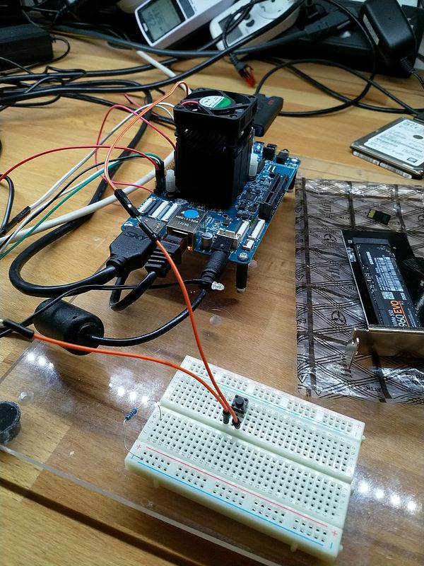
Wenn der Taster im Bild betätigt wird, soll die LED blinken.
Script
Wir benutzen folgende Ein- Augänge des ROCKPro64.
 # Set Variables
 var_gpio_out = 156
 var_gpio_in = 155
Das heißt:
- an Pin 1 (3,3V) kommt eine Strippe des Tasters
- an Pin 29 (Input) kommt eine Strippe des Tasters
- an Pin 31 (Putput) kommt der Plus-Pol der LED
- an Pin 39 (GND) kommt der Minus-Pol der LED
Somit wird auf den Eingang (Pin 29) bei Betätigung des Tasters 3,3 Volt angelegt. Damit wird dann der Eingang als High (1) erkannt. Die LED wird über den Ausgang (Pin 31) gesteuert.
#!/usr/bin/env python # Frank Mankel, 2018, LGPLv3 License # Rock 64 GPIO Library for Python # Thanks Allison! Thanks smartdave! import R64.GPIO as GPIO from time import sleep print("Output Test R64.GPIO Module...") # Set Variables var_gpio_out = 156 var_gpio_in = 155 # GPIO Setup GPIO.setwarnings(True) GPIO.setmode(GPIO.ROCK) GPIO.setup(var_gpio_out, GPIO.OUT, initial=GPIO.HIGH) # Set up GPIO as an output, with an initial state of HIGH GPIO.setup(var_gpio_in, GPIO.IN, pull_up_down=GPIO.PUD_UP) # Set up GPIO as an input, pullup enabled # Test Output print("") print("Testing GPIO Input/Output:") while True: var_gpio_state_in = GPIO.input(var_gpio_in) var_gpio_state = GPIO.input(var_gpio_out) # Return State of GPIO if var_gpio_state == str(0) and var_gpio_state_in == str(1): GPIO.output(var_gpio_out,1) # Set GPIO to HIGH print("Input State: " + str(var_gpio_state_in)) # Print results print("Output State IF : " + str(var_gpio_state)) # Print results else: GPIO.output(var_gpio_out,0) # Set GPIO to LOW print("Input State: " + str(var_gpio_state_in)) # Print results print("Output State ELSE: " + str(var_gpio_state)) # Print results sleep(0.5) exit() -
Das Projekt (ein Fork) ist aktualisiert und kann jetzt für den ROCK64 und den ROCKPro64 benutzt werden.
Rock64-R64.GPIO/R64/_GPIO.py at master · mrfixit2001/Rock64-R64.GPIO
Python GPIO library for the Rock64 and RockPro64 SBC (RPi.GPIO clone) - Rock64-R64.GPIO/R64/_GPIO.py at master · mrfixit2001/Rock64-R64.GPIO

GitHub (github.com)
Mit
setrock('ROCKPRO64')kann man das Script für den ROCKPro64 anpassen.
Quelle: https://forum.pine64.org/showthread.php?tid=6419&pid=41270#pid41270
Sobald ich mal Zeit und Lust habe, werde ich das Testen und hier berichten.
-
Die Coderin von dieser Library Leapo schreibt folgendes
For anyone using my GPIO library: Just fixed a pretty major bug with GPIO.input, where it would return "1" or "0" as a string rather than as an integer. This fix greatly improves compatibility with scripts written originally for RPI.GPIO. Edit: I've also also fixed Python 3 compatibility (library would crash-out under python 3 if certain debug text was called for).
Quelle: discordapp.com
Für den ein oder anderen, der das nutzt vermutlich sehr interessant.
-
Hallo zusammen,
da ich weiß das dieser Artikel recht beliebt ist, wollen wir den heute mal aktualisieren. Vieles aus den vorherigen Beiträgen passt noch. Es gibt aber kleine Anpassungen.
Hardware
- ROCKPro64v21. 2GB RAM
Software
- Kamils Release 0.10.9
- Linux rockpro64 5.6.0-1132-ayufan-g81043e6e109a #ayufan SMP Tue Apr 7 10:07:35 UTC 2020 aarch64 GNU/Linux
Installation
apt install pythonDanach laden wir das Projekt
git clone https://github.com/Leapo/Rock64-R64.GPIOPIN Nummern anpassen
cd Rock64-R64.GPIO/R64
nano _GPIO.py
Datei ergänzen
# Define GPIO arrays
#ROCK_valid_channels = [27, 32, 33, 34, 35, 36, 37, 38, 64, 65, 67, 68, 69, 76, 79, 80, 81, 82, 83, 84, 85, 86, 87, 88, 89, 96, 97, 98, 100, 101, 102, 103, 104]
#BOARD_to_ROCK = [0, 0, 0, 89, 0, 88, 0, 0, 64, 0, 65, 0, 67, 0, 0, 100, 101, 0, 102, 97, 0, 98, 103, 96, 104, 0, 76, 68, 69, 0, 0, 0, 38, 32, 0, 33, 37, 34, 36, 0, 35, 0, 0, 81, 82, 87, 83, 0, 0, 80, 79, 85, 84, 27, 86, 0, 0, 0, 0, 0, 0, 89, 88]
#BCM_to_ROCK = [68, 69, 89, 88, 81, 87, 83, 76, 104, 98, 97, 96, 38, 32, 64, 65, 37, 80, 67, 33, 36, 35, 100, 101, 102, 103, 34, 82]
ROCK_valid_channels = [52,53,152,54,50,33,48,39,41,43,155,156,125,122,121,148,147,120,36,149,153,42,45,44,124,126,123,127]
BOARD_to_ROCK = [0,0,0,52,0,53,0,152,148,0,147,54,120,50,0,33,36,0,149,48,0,39,153,41,42,0,45,43,44,155,0,156,124,125,0,122,126,121,123,0,127]
BCM_to_ROCK = [43,44,52,53,152,155,156,45,42,39,48,41,124,125,148,147,124,54,120,122,123,127,33,36,149,153,121,50]
Abspeichern.
Datei test.py anlegen
nano test.pyInhalt
#!/usr/bin/env python

# Frank Mankel, 2018, LGPLv3 License
# Rock 64 GPIO Library for Python
# Thanks Allison! Thanks smartdave!

import R64.GPIO as GPIO
from time import sleep

print("Output Test R64.GPIO Module...")

# Set Variables
var_gpio_out = 156
var_gpio_in = 155


# GPIO Setup
GPIO.setwarnings(True)
GPIO.setmode(GPIO.ROCK)
GPIO.setup(var_gpio_out, GPIO.OUT, initial=GPIO.HIGH)       # Set up GPIO as an output, with an initial state of HIGH
GPIO.setup(var_gpio_in, GPIO.IN, pull_up_down=GPIO.PUD_UP)  # Set up GPIO as an input, pullup enabled

# Test Output
print("")
print("Testing GPIO Input/Output:")


while True:
        var_gpio_state_in = GPIO.input(var_gpio_in)
        var_gpio_state = GPIO.input(var_gpio_out)                       # Return State of GPIO
        if var_gpio_state == 0 and var_gpio_state_in == 1:
                GPIO.output(var_gpio_out,GPIO.HIGH)                             # Set GPIO to HIGH
                print("Input State: " + str(var_gpio_state_in))         # Print results
                print("Output State IF : " + str(var_gpio_state))       # Print results
        else:
                GPIO.output(var_gpio_out,GPIO.LOW)                             # Set GPIO to LOW
                print("Input State: " + str(var_gpio_state_in))         # Print results
                print("Output State ELSE: " + str(var_gpio_state))      # Print results
        sleep(0.5)
exit()
Beispiel
Wenn der Taster im Bild betätigt wird, soll die LED blinken.
Wir benutzen folgende Ein- Augänge des ROCKPro64.
# Set Variables
var_gpio_out = 156
var_gpio_in = 155
Das heißt:
- an Pin 1 (3,3V) kommt eine Strippe des Tasters
- an Pin 29 (Input) kommt eine Strippe des Tasters
- an Pin 31 (Output) kommt der Plus-Pol der LED
- an Pin 39 (GND) kommt der Minus-Pol der LED
Somit wird auf den Eingang (Pin 29) bei Betätigung des Tasters 3,3 Volt angelegt. Damit wird dann der Eingang als High (1) erkannt. Die LED wird über den Ausgang (Pin 31) gesteuert.
Starten kann man das Script mit
python test.py
-
-
-
-
-
-
-
stretch-minimal-rockpro64
Verschoben Linux -