Skip to content

DTS DTB Files bearbeiten

Angeheftet ROCKPro64
3 1 1.7k
  • ACHTUNG, nur was für erfahrene Nutzer. Beschädigungen der Hardware nicht ausgeschlossen!! Also, Hirn einschalten!!

    Diese kleinen Platinen haben ja unzählige Funktionen, Ein- und Ausgänge usw. Das ganze muss ja irgendwie konfiguriert werden. Auf den ARM-Boards macht man das mit DTB Files.

    Wir nehmen mal eine geflashte SD-Karte und stecken die in einen Kartenleser. Dann öffnen wir die Boot Partition.

     frank@frank-MS-7A34 /media/frank/boot $ ls -la
     insgesamt 25272
     drwxr-xr-x  3 frank frank    16384 Jan  1  1970 .
     drwxr-x---+ 3 root  root      4096 Jun 13 13:35 ..
     -rw-r--r--  1 frank frank    69042 Jun 13 13:00 dtb
     drwxr-xr-x  2 frank frank     2048 Jun 10 20:44 extlinux
     -rw-r--r--  1 frank frank 19425288 Jun 10 20:45 Image
     -rw-r--r--  1 frank frank  6358282 Jun 10 20:45 initrd.img
    

    Das File was uns interessiert ist das File mit dem Namen dtb Dieses File kann man aber nicht so ohne weiteres bearbeiten, wie aber so oft unter Linux, gibt es für fast alles ein Tool. In diesem Fall heißt das Tool dtc (devive tree compiler) Das kann man so installieren.

    sudo apt-get install device-tree-compiler
    

    Dieser Compiler kann aus dem File dtb, was ein Binärfile ist, ein lesbares Textfile generieren und anders rum.

    Aus dem dtb File ein lesbares File erzeugen!

    cp /media/frank/boot/dtb /home/frank/dts
    dtc -I dtb -O dts -o testfile dtb
    
    • /media/frank/boot ist der Mountpoint
    • /home/frank/dts ist mein Testordner zum Spielen

    In dem Beispiel kopiere ich das File dtb von der SD-Karte in mein Testverzeichnis. Im nächsten Schritt wird dann aus dem dtb File das lesbare Textfile mit Namen testfile erzeugt.

    Dieses könnt ihr dann mit Eurem Lieblings Texteditor öffnen.

    code testfile
    

    Dann ist die Datei lesbar und änderbar.

    Beispiel (gekürzt)

    /dts-v1/;
    
    / {
    	compatible = "pine64,rockpro64", "rockchip,rk3399";
    	interrupt-parent = <0x1>;
    	#address-cells = <0x2>;
    	#size-cells = <0x2>;
    	model = "Pine64 RockPro64";
    
    	ddr_timing {
    		compatible = "rockchip,ddr-timing";
    		ddr3_speed_bin = <0x15>;
    		pd_idle = <0x0>;
    		sr_idle = <0x0>;
    		sr_mc_gate_idle = <0x0>;
    		srpd_lite_idle = <0x0>;
    		standby_idle = <0x0>;
    		auto_lp_dis_freq = <0x29a>;
    		ddr3_dll_dis_freq = <0x12c>;
    		phy_dll_dis_freq = <0x104>;
    		ddr3_odt_dis_freq = <0x29a>;
    		ddr3_drv = <0x28>;
    		ddr3_odt = <0x78>;
    		phy_ddr3_ca_drv = <0x28>;
    		phy_ddr3_dq_drv = <0x28>;
    		phy_ddr3_odt = <0xf0>;
    		lpddr3_odt_dis_freq = <0x29a>;
    		lpddr3_drv = <0x22>;
    		lpddr3_odt = <0xf0>;
    		phy_lpddr3_ca_drv = <0x22>;
    		phy_lpddr3_dq_drv = <0x22>;
    		phy_lpddr3_odt = <0xf0>;
    		lpddr4_odt_dis_freq = <0x320>;
    		lpddr4_drv = <0xf0>;
    		lpddr4_dq_odt = <0x28>;
    		lpddr4_ca_odt = <0x0>;
    		phy_lpddr4_ca_drv = <0x28>;
    		phy_lpddr4_ck_cs_drv = <0x28>;
    		phy_lpddr4_dq_drv = <0x3c>;
    		phy_lpddr4_odt = <0x28>;
    		phandle = <0x8f>;
    	};
    
    	aliases {
    		i2c0 = "/i2c@ff3c0000";
    		i2c1 = "/i2c@ff110000";
    		i2c2 = "/i2c@ff120000";
    		i2c3 = "/i2c@ff130000";
    		i2c4 = "/i2c@ff3d0000";
    		i2c5 = "/i2c@ff140000";
    		i2c6 = "/i2c@ff150000";
    		i2c7 = "/i2c@ff160000";
    		i2c8 = "/i2c@ff3e0000";
    		serial0 = "/serial@ff180000";
    		serial1 = "/serial@ff190000";
    		serial2 = "/serial@ff1a0000";
    		serial3 = "/serial@ff1b0000";
    		serial4 = "/serial@ff370000";
    		dsi0 = "/dsi@ff960000";
    		dsi1 = "/dsi@ff968000";
    		ethernet0 = "/ethernet@fe300000";
    	};
    
    	cpus {
    		#address-cells = <0x2>;
    		#size-cells = <0x0>;
    
    		cpu-map {
    
    			cluster0 {
    
    				core0 {
    					cpu = <0x2>;
    				};
    
    				core1 {
    					cpu = <0x3>;
    				};
    
    				core2 {
    					cpu = <0x4>;
    				};
    
    				core3 {
    					cpu = <0x5>;
    				};
    			};
    
    			cluster1 {
    
    				core0 {
    					cpu = <0x6>;
    				};
    
    				core1 {
    					cpu = <0x7>;
    				};
    			};
    		};
    
    		cpu@0 {
    			device_type = "cpu";
    			compatible = "arm,cortex-a53", "arm,armv8";
    			reg = <0x0 0x0>;
    			enable-method = "psci";
    			#cooling-cells = <0x2>;
    			dynamic-power-coefficient = <0x64>;
    			clocks = <0x8 0x8>;
    			cpu-idle-states = <0x9 0xa>;
    			operating-points-v2 = <0xb>;
    			sched-energy-costs = <0xc 0xd>;
    			cpu-supply = <0xe>;
    			phandle = <0x2>;
    		};
    
    		cpu@1 {
    			device_type = "cpu";
    			compatible = "arm,cortex-a53", "arm,armv8";
    			reg = <0x0 0x1>;
    			enable-method = "psci";
    			clocks = <0x8 0x8>;
    			cpu-idle-states = <0x9 0xa>;
    			operating-points-v2 = <0xb>;
    			sched-energy-costs = <0xc 0xd>;
    			cpu-supply = <0xe>;
    			phandle = <0x3>;
    		};
    
    		cpu@2 {
    			device_type = "cpu";
    			compatible = "arm,cortex-a53", "arm,armv8";
    			reg = <0x0 0x2>;
    			enable-method = "psci";
    			clocks = <0x8 0x8>;
    			cpu-idle-states = <0x9 0xa>;
    			operating-points-v2 = <0xb>;
    			sched-energy-costs = <0xc 0xd>;
    			cpu-supply = <0xe>;
    			phandle = <0x4>;
    		};
    
    		cpu@3 {
    			device_type = "cpu";
    			compatible = "arm,cortex-a53", "arm,armv8";
    			reg = <0x0 0x3>;
    			enable-method = "psci";
    			clocks = <0x8 0x8>;
    			cpu-idle-states = <0x9 0xa>;
    			operating-points-v2 = <0xb>;
    			sched-energy-costs = <0xc 0xd>;
    			cpu-supply = <0xe>;
    			phandle = <0x5>;
    		};
    
    		cpu@100 {
    			device_type = "cpu";
    			compatible = "arm,cortex-a72", "arm,armv8";
    			reg = <0x0 0x100>;
    			enable-method = "psci";
    			#cooling-cells = <0x2>;
    			dynamic-power-coefficient = <0x1b4>;
    			clocks = <0x8 0x9>;
    			cpu-idle-states = <0x9 0xa>;
    			operating-points-v2 = <0xf>;
    			sched-energy-costs = <0x10 0x11>;
    			cpu-supply = <0x12>;
    			phandle = <0x6>;
    		};
    
    		cpu@101 {
    			device_type = "cpu";
    			compatible = "arm,cortex-a72", "arm,armv8";
    			reg = <0x0 0x101>;
    			enable-method = "psci";
    			clocks = <0x8 0x9>;
    			cpu-idle-states = <0x9 0xa>;
    			operating-points-v2 = <0xf>;
    			sched-energy-costs = <0x10 0x11>;
    			cpu-supply = <0x12>;
    			phandle = <0x7>;
    		};
    
    		idle-states {
    			entry-method = "psci";
    
    			cpu-sleep {
    				compatible = "arm,idle-state";
    				local-timer-stop;
    				arm,psci-suspend-param = <0x10000>;
    				entry-latency-us = <0x78>;
    				exit-latency-us = <0xfa>;
    				min-residency-us = <0x384>;
    				phandle = <0x9>;
    			};
    
    			cluster-sleep {
    				compatible = "arm,idle-state";
    				local-timer-stop;
    				arm,psci-suspend-param = <0x1010000>;
    				entry-latency-us = <0x190>;
    				exit-latency-us = <0x1f4>;
    				min-residency-us = <0x7d0>;
    				phandle = <0xa>;
    			};
    		};
    	};
    
    	pmu_a53 {
    		compatible = "arm,cortex-a53-pmu";
    		interrupts = <0x1 0x7 0x8 0x13>;
    	};
    
    	pmu_a72 {
    		compatible = "arm,cortex-a72-pmu";
    		interrupts = <0x1 0x7 0x8 0x14>;
    	};
    
    	psci {
    		compatible = "arm,psci-1.0";
    		method = "smc";
    	};
    
    	timer {
    		compatible = "arm,armv8-timer";
    		interrupts = <0x1 0xd 0x8 0x0 0x1 0xe 0x8 0x0 0x1 0xb 0x8 0x0 0x1 0xa 0x8 0x0>;
    	};
    
    	xin24m {
    		compatible = "fixed-clock";
    		clock-frequency = <0x16e3600>;
    		clock-output-names = "xin24m";
    		#clock-cells = <0x0>;
    	};
    
    	dummy_cpll {
    		compatible = "fixed-clock";
    		clock-frequency = <0x0>;
    		clock-output-names = "dummy_cpll";
    		#clock-cells = <0x0>;
    	};
    
    	dummy_vpll {
    		compatible = "fixed-clock";
    		clock-frequency = <0x0>;
    		clock-output-names = "dummy_vpll";
    		#clock-cells = <0x0>;
    	};
    
    	amba {
    		compatible = "arm,amba-bus";
    		#address-cells = <0x2>;
    		#size-cells = <0x2>;
    		ranges;
    
    		dma-controller@ff6d0000 {
    			compatible = "arm,pl330", "arm,primecell";
    			reg = <0x0 0xff6d0000 0x0 0x4000>;
    			interrupts = <0x0 0x5 0x4 0x0 0x0 0x6 0x4 0x0>;
    			#dma-cells = <0x1>;
    			clocks = <0x8 0xd3>;
    			clock-names = "apb_pclk";
    			peripherals-req-type-burst;
    			phandle = <0x98>;
    		};
    
    		dma-controller@ff6e0000 {
    			compatible = "arm,pl330", "arm,primecell";
    			reg = <0x0 0xff6e0000 0x0 0x4000>;
    			interrupts = <0x0 0x7 0x4 0x0 0x0 0x8 0x4 0x0>;
    			#dma-cells = <0x1>;
    			clocks = <0x8 0xd4>;
    			clock-names = "apb_pclk";
    			peripherals-req-type-burst;
    		};
    	};
    
    	ethernet@fe300000 {
    		compatible = "rockchip,rk3399-gmac";
    		reg = <0x0 0xfe300000 0x0 0x10000>;
    		rockchip,grf = <0x15>;
    		interrupts = <0x0 0xc 0x4 0x0>;
    		interrupt-names = "macirq";
    		clocks = <0x8 0x69 0x8 0x67 0x8 0x68 0x8 0x66 0x8 0x6a 0x8 0xd5 0x8 0x166>;
    		clock-names = "stmmaceth", "mac_clk_rx", "mac_clk_tx", "clk_mac_ref", "clk_mac_refout", "aclk_mac", "pclk_mac";
    		resets = <0x8 0x89>;
    		reset-names = "stmmaceth";
    		power-domains = <0x16 0x16>;
    		status = "okay";
    		phy-supply = <0x17>;
    		phy-mode = "rgmii";
    		clock_in_out = "input";
    		snps,reset-gpio = <0x18 0xf 0x1>;
    		snps,reset-active-low;
    		snps,reset-delays-us = <0x0 0x2710 0xc350>;
    		assigned-clocks = <0x8 0xa6>;
    		assigned-clock-parents = <0x19>;
    		pinctrl-names = "default", "sleep";
    		pinctrl-0 = <0x1a>;
    		pinctrl-1 = <0x1b>;
    		tx_delay = <0x28>;
    		rx_delay = <0x20>;
    	};
    
    	dwmmc@fe310000 {
    		compatible = "rockchip,rk3399-dw-mshc", "rockchip,rk3288-dw-mshc";
    		reg = <0x0 0xfe310000 0x0 0x4000>;
    		interrupts = <0x0 0x40 0x4 0x0>;
    		clock-freq-min-max = <0x30d40 0x2faf080>;
    		clocks = <0x8 0x1ee 0x8 0x4d 0x8 0x9c 0x8 0x9d>;
    		clock-names = "biu", "ciu", "ciu-drive", "ciu-sample";
    		fifo-depth = <0x100>;
    		power-domains = <0x16 0x1c>;
    		status = "okay";
    		clock-frequency = <0x2faf080>;
    		supports-sdio;
    		bus-width = <0x4>;
    		disable-wp;
    		cap-sd-highspeed;
    		cap-sdio-irq;
    		keep-power-in-suspend;
    		mmc-pwrseq = <0x1c>;
    		non-removable;
    		num-slots = <0x1>;
    		pinctrl-names = "default";
    		pinctrl-0 = <0x1d 0x1e 0x1f>;
    		sd-uhs-sdr104;
    	};
    
    	dwmmc@fe320000 {
    		compatible = "rockchip,rk3399-dw-mshc", "rockchip,rk3288-dw-mshc";
    		reg = <0x0 0xfe320000 0x0 0x4000>;
    		interrupts = <0x0 0x41 0x4 0x0>;
    		clock-freq-min-max = <0x61a80 0x8f0d180>;
    		clocks = <0x8 0x1ce 0x8 0x4c 0x8 0x9a 0x8 0x9b>;
    		clock-names = "biu", "ciu", "ciu-drive", "ciu-sample";
    		fifo-depth = <0x100>;
    		power-domains = <0x16 0x1b>;
    		status = "okay";
    		clock-frequency = <0x2faf080>;
    		supports-sd;
    		bus-width = <0x4>;
    		cap-mmc-highspeed;
    		cap-sd-highspeed;
    		disable-wp;
    		num-slots = <0x1>;
    		vqmmc-supply = <0x20>;
    		pinctrl-names = "default";
    		pinctrl-0 = <0x21 0x22 0x23 0x24>;
    		card-detect-delay = <0x320>;
    	};
    
    	sdhci@fe330000 {
    		compatible = "rockchip,rk3399-sdhci-5.1", "arasan,sdhci-5.1";
    		reg = <0x0 0xfe330000 0x0 0x10000>;
    		interrupts = <0x0 0xb 0x4 0x0>;
    		arasan,soc-ctl-syscon = <0x15>;
    		assigned-clocks = <0x8 0x4e>;
    		assigned-clock-rates = <0xbebc200>;
    		clocks = <0x8 0x4e 0x8 0xf0>;
    		clock-names = "clk_xin", "clk_ahb";
    		clock-output-names = "emmc_cardclock";
    		#clock-cells = <0x0>;
    		phys = <0x25>;
    		phy-names = "phy_arasan";
    		power-domains = <0x16 0x17>;
    		status = "okay";
    		bus-width = <0x8>;
    		mmc-hs200-1_8v;
    		supports-emmc;
    		non-removable;
    		keep-power-in-suspend;
    		phandle = <0x96>;
    	};
    

    Das dts des ROCKPro64. Nun kann man die Änderungen vornehmen und abspeichern. Danach muss man das File wieder in das Binärformat umwandeln.

    Aus dem testfile wieder ein dtb File erzeugen!

    dtc -I dts -O dtb -o dtb testfile
    cp /home/frank/dts/dtb /media/frank/boot
    

    Sollte selbsterklärend sein, macht aus dem testfile wieder ein dtb und kopiert es auf die SD-Karte zurück.

    Danach kann man dann seine Änderungen ausprobieren.

  • Hat sich was geändert?

    Neuer Pfad:

    cd /boot/dtbs/4.4.132-1066-rockchip-ayufan-g48b9d1455011/rockchip
    

    Übersetzen

    dtc -I dtb -O dts -f rk3399-rockpro64.dtb -o testfile.dts
    

    Bearbeiten

    code testfile.dts
    

    Zurück

     dtc -I dts -O dtb -f testfile.dts -o rk3399-rockpro64.dtb
    
  • Oder, ganz einfach

    sudo dtedit
    

    🙂

  • FrankMF FrankM hat am auf dieses Thema verwiesen
  • ROCKPro64: NAS mit PCI-e SATA-III Aufrüsten

    ROCKPro64 rockpro64
    13
    0 Stimmen
    13 Beiträge
    1k Aufrufe
    N
    @frankm Alles Klar! Wie schon erwähnt, für meine Zwecke rechts! Die Jahre über hat gute Dienste geleistet (PCI-e und HDD) und wird hoffentlich auch noch ein paar Jahre bis zum nächsten Umbau tun! Vielen Dank!
  • ROCKPro64 - Zwei LAN Schnittstellen / VLAN einrichten

    ROCKPro64 linux vlan rockpro64
    4
    0 Stimmen
    4 Beiträge
    698 Aufrufe
    FrankMF
    Das Setup heute mal getestet um zu sehen, ob das auch so funktioniert. LAN an meine Fritzbox (DHCP) an eth1.100 mein Notebook an eth1.200 meine PS4 Und dann mal gemütlich eine Runde MW gezockt. Läuft alles einwandfrei
  • ROCKPro64 - Kernel 5.3.0-rc4-1117 angetestet!

    ROCKPro64 rockpro64
    1
    0 Stimmen
    1 Beiträge
    416 Aufrufe
    Niemand hat geantwortet
  • ROCKPro64 - Das erste Mal

    Angeheftet Verschoben Hardware rockpro64
    5
    2
    1 Stimmen
    5 Beiträge
    997 Aufrufe
    FrankMF
    Ich kann heute die Fragen aller Fragen beantworten Damit ist leider die Frage immer noch unbeantwortet ob WLan und PCIe zusammen nutzbar ist!! Es geht!! Ich habe von MrFixit ein Testimage der RecalBox, benutzt das selbe Debian wie oben. Die Tage konnte man im IRC verfolgen, wie man dem Grundproblem näher kam und wohl einen Fix gebastelt hat, damit beides zusammen funktioniert. Mr.Fixit hat das in RecalBox eingebaut und ich durfte testen. # ip a 1: lo: <LOOPBACK,UP,LOWER_UP> mtu 65536 qdisc noqueue qlen 1 link/loopback 00:00:00:00:00:00 brd 00:00:00:00:00:00 inet 127.0.0.1/8 scope host lo valid_lft forever preferred_lft forever inet6 ::1/128 scope host valid_lft forever preferred_lft forever 2: eth0: <NO-CARRIER,BROADCAST,MULTICAST,UP8000> mtu 1500 qdisc pfifo_fast qlen 1000 link/ether 62:03:b0:d6:dc:b3 brd ff:ff:ff:ff:ff:ff 3: wlan0: <BROADCAST,MULTICAST,UP,LOWER_UP8000> mtu 1500 qdisc pfifo_fast qlen 1000 link/ether ac:83:f3:e6:1f:b2 brd ff:ff:ff:ff:ff:ff inet 192.168.178.27/24 brd 192.168.178.255 scope global wlan0 valid_lft forever preferred_lft forever inet6 2a02:908:1262:4680:ae83:f3ff:fee6:1fb2/64 scope global dynamic valid_lft 7145sec preferred_lft 3545sec inet6 fe80::ae83:f3ff:fee6:1fb2/64 scope link valid_lft forever preferred_lft forever # ls /mnt bin etc media recalbox sd.img test2.img boot home mnt root selinux tmp crypthome lib opt run srv usr dev lost+found proc sbin sys var # fdisk BusyBox v1.27.2 (2019-02-01 22:43:19 EST) multi-call binary. Usage: fdisk [-ul] [-C CYLINDERS] [-H HEADS] [-S SECTORS] [-b SSZ] DISK Change partition table -u Start and End are in sectors (instead of cylinders) -l Show partition table for each DISK, then exit -b 2048 (for certain MO disks) use 2048-byte sectors -C CYLINDERS Set number of cylinders/heads/sectors -H HEADS Typically 255 -S SECTORS Typically 63 # fdisk -l Disk /dev/mmcblk0: 15 GB, 15931539456 bytes, 31116288 sectors 486192 cylinders, 4 heads, 16 sectors/track Units: cylinders of 64 * 512 = 32768 bytes Device Boot StartCHS EndCHS StartLBA EndLBA Sectors Size Id Type /dev/mmcblk0p1 * 2,10,9 10,50,40 32768 163839 131072 64.0M c Win95 FAT32 (LBA) Partition 1 does not end on cylinder boundary /dev/mmcblk0p2 * 16,81,2 277,102,17 262144 4456447 4194304 2048M 83 Linux Partition 2 does not end on cylinder boundary /dev/mmcblk0p3 277,102,18 1023,254,63 4456448 31115263 26658816 12.7G 83 Linux Partition 3 does not end on cylinder boundary Disk /dev/nvme0n1: 233 GB, 250059350016 bytes, 488397168 sectors 2543735 cylinders, 12 heads, 16 sectors/track Units: cylinders of 192 * 512 = 98304 bytes Device Boot StartCHS EndCHS StartLBA EndLBA Sectors Size Id Type /dev/nvme0n1p1 1,0,1 907,11,16 2048 488397167 488395120 232G 83 Linux # Oben sieht man eine funktionierende WLan-Verbindung, das LAN-Kabel war entfernt. Unten sieht man die PCIe NVMe SSD, gemountet nach /mnt und Inhaltsausgabe. Das sollte beweisen, das der Ansatz der Lösung funktioniert. Leider kann ich nicht sagen, das es zum jetzigen Zeitpunkt stabil läuft. Ich habe einfach so Reboots, kann den Fehler aktuell aber nicht fangen. Mal sehen ob ich noch was finde. Aber, es ist ein Anfang!
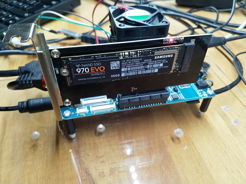
  • ROCKPro64 - Samsung 970 NVMe M.2 500GB

    Hardware hardware rockpro64
    1
    1
    0 Stimmen
    1 Beiträge
    1k Aufrufe
    Niemand hat geantwortet
  • Tehuti Networks Ltd. TN9710P 10GBase-T/NBASE-T Ethernet Adapter

    Hardware hardware rockpro64
    2
    0 Stimmen
    2 Beiträge
    2k Aufrufe
    FrankMF
    This repo contains the tn40xx Linux driver for 10Gbit NICs based on the TN4010 MAC from Tehuti Networks. This driver enables the following 10Gb SFP+ NICs: D-Link DXE-810S Edimax EN-9320SFP+ StarTech PEX10000SFP Synology E10G15-F1 ... as well as the following 10GBase-T/NBASE-T NICs: D-Link DXE-810T Edimax EN-9320TX-E EXSYS EX-6061-2 Intellinet 507950 StarTech ST10GSPEXNB Quelle: https://github.com/ayufan-rock64/tn40xx-driver/tree/master
  • ROCKPro64 - RP64.GPIO

    Angeheftet Verschoben Hardware hardware rockpro64
    6
    1
    0 Stimmen
    6 Beiträge
    6k Aufrufe
    FrankMF
    Hallo zusammen, da ich weiß das dieser Artikel recht beliebt ist, wollen wir den heute mal aktualisieren. Vieles aus den vorherigen Beiträgen passt noch. Es gibt aber kleine Anpassungen. Hardware ROCKPro64v21. 2GB RAM Software Kamils Release 0.10.9 Linux rockpro64 5.6.0-1132-ayufan-g81043e6e109a #ayufan SMP Tue Apr 7 10:07:35 UTC 2020 aarch64 GNU/Linux Installation apt install python Danach laden wir das Projekt git clone https://github.com/Leapo/Rock64-R64.GPIO PIN Nummern anpassen cd Rock64-R64.GPIO/R64 nano _GPIO.py Datei ergänzen # Define GPIO arrays #ROCK_valid_channels = [27, 32, 33, 34, 35, 36, 37, 38, 64, 65, 67, 68, 69, 76, 79, 80, 81, 82, 83, 84, 85, 86, 87, 88, 89, 96, 97, 98, 100, 101, 102, 103, 104] #BOARD_to_ROCK = [0, 0, 0, 89, 0, 88, 0, 0, 64, 0, 65, 0, 67, 0, 0, 100, 101, 0, 102, 97, 0, 98, 103, 96, 104, 0, 76, 68, 69, 0, 0, 0, 38, 32, 0, 33, 37, 34, 36, 0, 35, 0, 0, 81, 82, 87, 83, 0, 0, 80, 79, 85, 84, 27, 86, 0, 0, 0, 0, 0, 0, 89, 88] #BCM_to_ROCK = [68, 69, 89, 88, 81, 87, 83, 76, 104, 98, 97, 96, 38, 32, 64, 65, 37, 80, 67, 33, 36, 35, 100, 101, 102, 103, 34, 82] ROCK_valid_channels = [52,53,152,54,50,33,48,39,41,43,155,156,125,122,121,148,147,120,36,149,153,42,45,44,124,126,123,127] BOARD_to_ROCK = [0,0,0,52,0,53,0,152,148,0,147,54,120,50,0,33,36,0,149,48,0,39,153,41,42,0,45,43,44,155,0,156,124,125,0,122,126,121,123,0,127] BCM_to_ROCK = [43,44,52,53,152,155,156,45,42,39,48,41,124,125,148,147,124,54,120,122,123,127,33,36,149,153,121,50] Abspeichern. Datei test.py anlegen nano test.py Inhalt #!/usr/bin/env python # Frank Mankel, 2018, LGPLv3 License # Rock 64 GPIO Library for Python # Thanks Allison! Thanks smartdave! import R64.GPIO as GPIO from time import sleep print("Output Test R64.GPIO Module...") # Set Variables var_gpio_out = 156 var_gpio_in = 155 # GPIO Setup GPIO.setwarnings(True) GPIO.setmode(GPIO.ROCK) GPIO.setup(var_gpio_out, GPIO.OUT, initial=GPIO.HIGH) # Set up GPIO as an output, with an initial state of HIGH GPIO.setup(var_gpio_in, GPIO.IN, pull_up_down=GPIO.PUD_UP) # Set up GPIO as an input, pullup enabled # Test Output print("") print("Testing GPIO Input/Output:") while True: var_gpio_state_in = GPIO.input(var_gpio_in) var_gpio_state = GPIO.input(var_gpio_out) # Return State of GPIO if var_gpio_state == 0 and var_gpio_state_in == 1: GPIO.output(var_gpio_out,GPIO.HIGH) # Set GPIO to HIGH print("Input State: " + str(var_gpio_state_in)) # Print results print("Output State IF : " + str(var_gpio_state)) # Print results else: GPIO.output(var_gpio_out,GPIO.LOW) # Set GPIO to LOW print("Input State: " + str(var_gpio_state_in)) # Print results print("Output State ELSE: " + str(var_gpio_state)) # Print results sleep(0.5) exit() Beispiel [image: 1537522070243-input_ergebnis.jpg] Wenn der Taster im Bild betätigt wird, soll die LED blinken. Wir benutzen folgende Ein- Augänge des ROCKPro64. # Set Variables var_gpio_out = 156 var_gpio_in = 155 Das heißt: an Pin 1 (3,3V) kommt eine Strippe des Tasters an Pin 29 (Input) kommt eine Strippe des Tasters an Pin 31 (Output) kommt der Plus-Pol der LED an Pin 39 (GND) kommt der Minus-Pol der LED Somit wird auf den Eingang (Pin 29) bei Betätigung des Tasters 3,3 Volt angelegt. Damit wird dann der Eingang als High (1) erkannt. Die LED wird über den Ausgang (Pin 31) gesteuert. Starten kann man das Script mit python test.py https://www.youtube.com/watch?v=aPSC0Q0xInw
  • Bionic Minimal 0.7.7 - Vergleich 4.4.132 & 4.18.0-rc3-1046

    Verschoben Archiv rockpro64
    1
    0 Stimmen
    1 Beiträge
    623 Aufrufe
    Niemand hat geantwortet