Serielle Konsole UART2
-
Hier mal die Info's sammeln zur seriellen Konsole.
- Baudrate: 1500000
- Data bits: 8
- Parity: N
- Stop bits: 1
Quelle: http://opensource.rock-chips.com/images/f/f9/RK3399_Linux_Debain_V1.1_Development_Guide170620.pdf
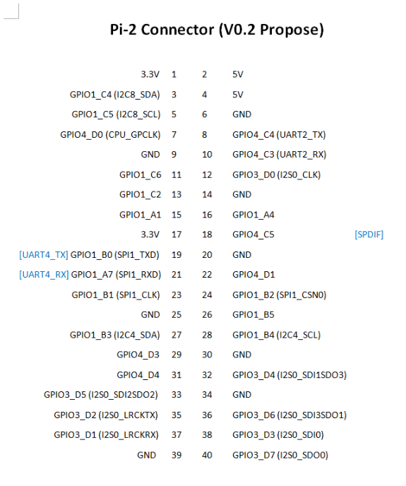
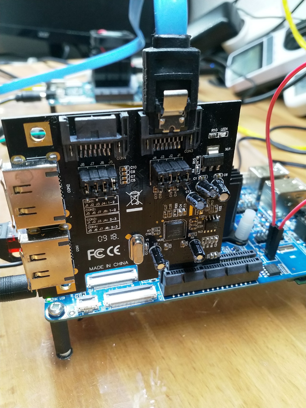
Es sieht so aus, das es auf den SOC's von Pine64 keinen separaten Steckplatz für die serielle Konsole gibt, so wie ich das von den Bananen her kenne. Man nutzt wohl direkt den UART2 Anschluss des Expansions Steckplatzes. Da hätten wir dann:
Die rote Ader nicht anschließen!
- Nr. 6 GND - schwarz
- Nr. 8 UART2_TX - weiß
- Nr. 10 UART2_ RX - grün
Update vom 18. März 2019
Seit dem Image 0.7.14 stört die Verbindung an Pin 10 das Booten des ROCKPro64, wenn dieser mit einem WiFi-Modul und einer PCIe-Karte bestückt ist. Das entfernen der Verbindung löst das Problem, man hat dann aber nur noch lesend Zugriff und kann keine Kommandos über die Konsole absetzen! Aber, das sollte das kleiner Problem sein. Die Entwickler sind informiert, keine Ahnung ob man das Fixen kann.

Als Gedankenstütze, vom ROCK64 https://forum.pine64.org/showthread.php?tid=5008
Damit sollten die vorhandenen USB-Adapter genauso wie bei den Bananen funktionieren!
Achtung!
Durch die schnelle Übertragungsrate kommt es bei verschiedenen Adaptern zu Darstellungsfehlern. Ein Adapter bei mir funktioniert nicht, fehlerhafte Darstellung. Mein billigster Adapter funktioniert, einwandfreie Darstellung.
Also, wenn ihr Probleme habt, einfach mal einen anderen Adapter ausprobieren. Die anderen Angaben oben funktionieren!
Tools zum Flashen
- Etcher etcher.io
- Pine64-Installer github.com
-
Ich habe ja einige Adapter ausprobiert, habe jetzt eine ordentliche Sammlung davon, aber habe jetzt einen gefunden der mir wohl alles anzeigt
")
Problem bei vielen Adaptern scheint die hohe Übertragungsrate zu sein. Wenn ihr als Ausgabe nur Müll bekommt, könnt ihr den Adapter direkt an die Seite legen, korrekter Anschluss vorausgesetzt!
Einen Adapter den ich jetzt die ganze Zeit benutzt hatte, war folgender.
Bus 003 Device 017: ID 10c4:ea60 Cygnal Integrated Products, Inc. CP210x UART Bridge / myAVR mySmartUSB lightGing, hatte aber das Problem das beim ersten Start die Ausgaben des U-Boots nicht vernünftig angezeigt werden. Wenn man mit den Platinen rumspielt, ist das sehr unvorteilhaft.
Ok, nächster Versuch
Bus 003 Device 016: ID 1a86:7523 QinHeng Electronics HL-340 USB-Serial adapterUnd der zeigt jetzt auch den U-Boot vernünftig an. Benutzt wird folgendes Linux.
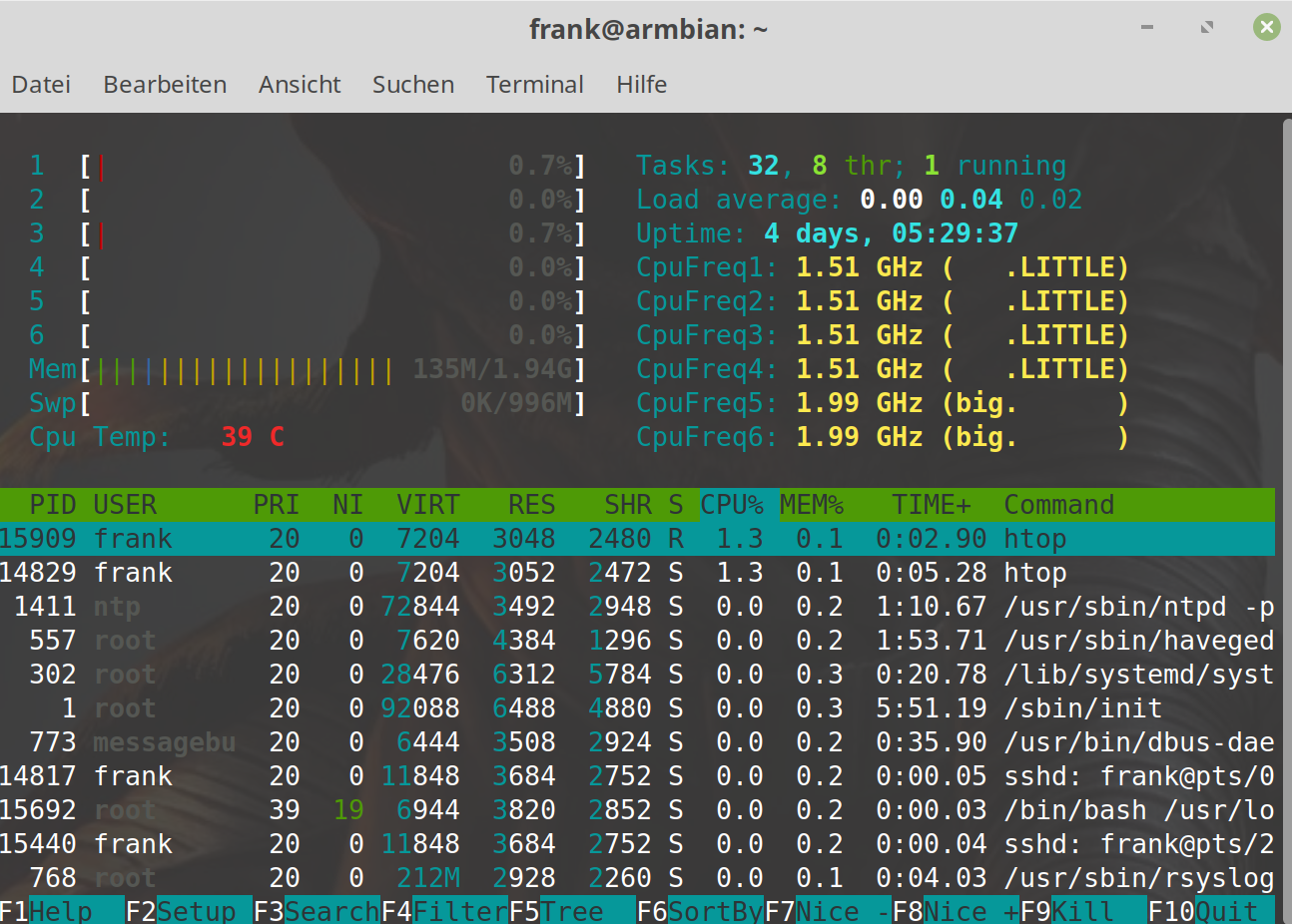
rock64@rockpro64:~$ uname -a
Linux rockpro64 4.4.126-rockchip-ayufan-239 #1 SMP Sun May 27 18:38:24 UTC 2018 aarch64 aarch64 aarch64 GNU/Linux
Ausgabe
channel 0 training pass!

channel 1 training pass!

change freq to 800MHz 1,0

ch 0 ddrconfig = 0x101, ddrsize = 0x2020

ch 1 ddrconfig = 0x101, ddrsize = 0x2020

pmugrf_os_reg[2] = 0x3AA1FAA1, stride = 0xD

OUT

U-Boot SPL board init


U-Boot SPL 2017.09-g03a332b (May 27 2018 - 18:34:10)

booted from SD

Trying to boot from MMC2

NOTICE:  BL31: v1.3(debug):d98d16e

NOTICE:  BL31: Built : 15:03:07, May 10 2018

NOTICE:  BL31: Rockchip release version: v1.1

INFO:    GICv3 with legacy support detected. ARM GICV3 driver initialized in EL3

INFO:    Using opteed sec cpu_context!

INFO:    boot cpu mask: 0

INFO:    plat_rockchip_pmu_init(1151): pd status 3e

INFO:    BL31: Initializing runtime services

WARNING: No OPTEE provided by BL2 boot loader, Booting device without OPTEE initialization. SMC`s destined for OPTEE will return SMC_UNK

ERROR:   Error initializing runtime service opteed_fast

INFO:    BL31: Preparing for EL3 exit to normal world

INFO:    Entry point address = 0x200000

INFO:    SPSR = 0x3c9


U-Boot 2017.09-g03a332b (May 27 2018 - 18:34:23 +0000), Build: jenkins-linux-build-rock-64-239
So muss das sein.
")
Mach ich selten, aber um es anderen etwas einfacher zu machen hier ein Amazon Link.
Anschluss
ROCKPro64 - Adapter
- GND (6) - GND
- TX (8) - RX
- RX (10) - TX
Zu Pin 10 bitte das Update im ersten Beitrag beachten!
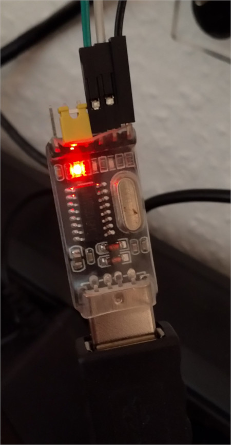
Die Brücke des Adapters steckt auf VCC / 3V3 und der Anschluss 5V ist frei. Das ist wohl ein Spannungsausgang, den man wahlweise auf 3V3 oder 5V schalten kann, den wir aber nicht benötigen!
Die Einstellungen der seriellen Schnittstelle findet ihr im Eingangsthread.
Ihr könnt natürlich, wenn ihr euch einen ROCKPro64 bestellt, direkt einen USB-Adapter mitbestellen!
https://www.pine64.org/?product=padi-serial-console
Ich setze mal voraus, das der funktioniert. -
@FrankM
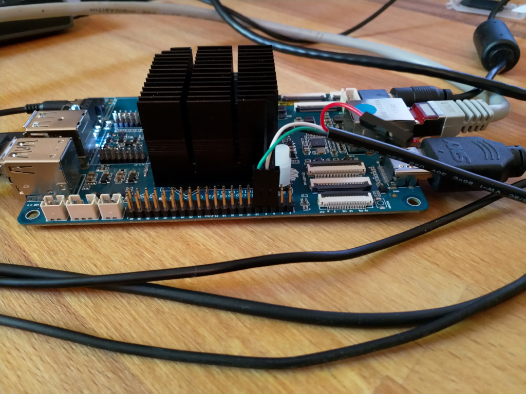
Der anschluss 10 RX auf dem Rockpro64 V2.1 und warscheinlich auch anderen da das auf deiner Seite irgendwo erwähnt wurde muss beim booten frei sein.Es sieht so aus als ob der Prozessor darüber Spannung bekommt da der TX pin vom adapter "high" gezogen wird da scheint ein fehler in dem Layout oder Prozessor zu sein so das eine versorgung durch diesen pin auch "Rückwärts" funktioniert.
Sehen kann man das wenn man GND und den pin 10 belegt, Spannung auf das Bord gibt und dann wieder trennt. Danach bleibt die Power LED leicht am glimmen. Nur anstecken des Serial converters reicht da nicht, dabei leuchtet die LED nicht auf. Außerdem geht das auch nur mit 5V Logic Level sonst kommt nicht genug an der LED an um es optisch zu erfassen das müsste man dann Messen, ist aber in jedem fall so nicht richtig.
Sven
-
@FrankM
Der anschluss 10 RX auf dem Rockpro64 V2.1 und warscheinlich auch anderen da das auf deiner Seite irgendwo erwähnt wurde muss beim booten frei sein.Es sieht so aus als ob der Prozessor darüber Spannung bekommt da der TX pin vom adapter "high" gezogen wird da scheint ein fehler in dem Layout oder Prozessor zu sein so das eine versorgung durch diesen pin auch "Rückwärts" funktioniert.
Sehen kann man das wenn man GND und den pin 10 belegt, Spannung auf das Bord gibt und dann wieder trennt. Danach bleibt die Power LED leicht am glimmen. Nur anstecken des Serial converters reicht da nicht, dabei leuchtet die LED nicht auf. Außerdem geht das auch nur mit 5V Logic Level sonst kommt nicht genug an der LED an um es optisch zu erfassen das müsste man dann Messen, ist aber in jedem fall so nicht richtig.
Sven
Hallo Sven,
ich muss mich zu dem Thema noch mal äußern.
Du hattest Recht!

Seit dem Image 0.7.14 (wifi & pcie) hatte ich das Problem das der ROCKPro64 nicht mehr booten möchte. Ein entfernen von Pin 10 löste das Problem.
Vielen Dank nachträglich!!
Nachteil, man kann von der Konsole aus nichts mehr machen!
Ich werde das in meinen Anleitungen entsprechend ändern!
-
Ich habe ja einige Adapter ausprobiert, habe jetzt eine ordentliche Sammlung davon, aber habe jetzt einen gefunden der mir wohl alles anzeigt
Problem bei vielen Adaptern scheint die hohe Übertragungsrate zu sein. Wenn ihr als Ausgabe nur Müll bekommt, könnt ihr den Adapter direkt an die Seite legen, korrekter Anschluss vorausgesetzt!
Einen Adapter den ich jetzt die ganze Zeit benutzt hatte, war folgender.
Bus 003 Device 017: ID 10c4:ea60 Cygnal Integrated Products, Inc. CP210x UART Bridge / myAVR mySmartUSB lightGing, hatte aber das Problem das beim ersten Start die Ausgaben des U-Boots nicht vernünftig angezeigt werden. Wenn man mit den Platinen rumspielt, ist das sehr unvorteilhaft.
Ok, nächster Versuch
Bus 003 Device 016: ID 1a86:7523 QinHeng Electronics HL-340 USB-Serial adapterUnd der zeigt jetzt auch den U-Boot vernünftig an. Benutzt wird folgendes Linux.
rock64@rockpro64:~$ uname -a
Linux rockpro64 4.4.126-rockchip-ayufan-239 #1 SMP Sun May 27 18:38:24 UTC 2018 aarch64 aarch64 aarch64 GNU/Linux
Ausgabe
channel 0 training pass!

channel 1 training pass!

change freq to 800MHz 1,0

ch 0 ddrconfig = 0x101, ddrsize = 0x2020

ch 1 ddrconfig = 0x101, ddrsize = 0x2020

pmugrf_os_reg[2] = 0x3AA1FAA1, stride = 0xD

OUT

U-Boot SPL board init


U-Boot SPL 2017.09-g03a332b (May 27 2018 - 18:34:10)

booted from SD

Trying to boot from MMC2

NOTICE:  BL31: v1.3(debug):d98d16e

NOTICE:  BL31: Built : 15:03:07, May 10 2018

NOTICE:  BL31: Rockchip release version: v1.1

INFO:    GICv3 with legacy support detected. ARM GICV3 driver initialized in EL3

INFO:    Using opteed sec cpu_context!

INFO:    boot cpu mask: 0

INFO:    plat_rockchip_pmu_init(1151): pd status 3e

INFO:    BL31: Initializing runtime services

WARNING: No OPTEE provided by BL2 boot loader, Booting device without OPTEE initialization. SMC`s destined for OPTEE will return SMC_UNK

ERROR:   Error initializing runtime service opteed_fast

INFO:    BL31: Preparing for EL3 exit to normal world

INFO:    Entry point address = 0x200000

INFO:    SPSR = 0x3c9


U-Boot 2017.09-g03a332b (May 27 2018 - 18:34:23 +0000), Build: jenkins-linux-build-rock-64-239
So muss das sein.
Mach ich selten, aber um es anderen etwas einfacher zu machen hier ein Amazon Link.
Anschluss
ROCKPro64 - Adapter
- GND (6) - GND
- TX (8) - RX
- RX (10) - TX
Zu Pin 10 bitte das Update im ersten Beitrag beachten!
Die Brücke des Adapters steckt auf VCC / 3V3 und der Anschluss 5V ist frei. Das ist wohl ein Spannungsausgang, den man wahlweise auf 3V3 oder 5V schalten kann, den wir aber nicht benötigen!
Die Einstellungen der seriellen Schnittstelle findet ihr im Eingangsthread.
Ihr könnt natürlich, wenn ihr euch einen ROCKPro64 bestellt, direkt einen USB-Adapter mitbestellen!
https://www.pine64.org/?product=padi-serial-console
Ich setze mal voraus, das der funktioniert.@FrankM
Hallo, ich bin noch ganz unerfahren mit Pi's.
Wenn ich jetzt eine Physische verbindung mit einer USB-TTL UART Konsole habe,
wie stelle ich da eine Verbindung her?
Ich habe Linux auch auf meinem Rechner drauf und bin nicht ganz begriffstuzig, was Konsolen angeht.
Vielen DankCri
-
Ich verweise mal auf einen Artikel auf einer Webseite von mir, der Einsteiger Niveau hat.
https://frank-mankel.de/wichtig/serielle-konsoleWenn es dann noch Probleme gibt, einfach fragen.
Und beachte bitte, das wir hier nicht über PIs schreiben, sondern über ROCKPros. Da könnte es kleine Unterschiede geben. https://www.raspberrypi.org/documentation/configuration/uart.md