Skip to content

ROCKPro64 - RP64.GPIO

Angeheftet Verschoben Hardware
  • Heute mal eine Bastelstunde und direkt vorne weg eine dicke fette Warnung!

    Hiermit kann man seinen ROCKPro64 in Elektroschrott verwandeln! Ich hafte nicht für Schäden! Hirn einschalten vorher! 😉

    0_1537440456037_IMG_20180920_124609_ergebnis.jpg

    Für den Rock64 gibt es ein Projekt das die RPi.GPIO cloned. https://github.com/Leapo/Rock64-R64.GPIO

    A Python GPIO library for the Rock64 single-board computer (RPi.GPIO clone).

    GPIO - was ist das? Wiki

    Gut, damit läuft das aber nicht auf einem ROCKPro64, weil die Nummerierungen der Pins nicht passen. Aber dafür gibt es da draußen Leute, die sich solche Themen erarbeiten.

    Quelle: https://forum.pine64.org/showthread.php?tid=6419&pid=40185#pid40185

    Erstmal das Ergebnis 🙂

    Output Test R64.GPIO Module...
    This channel (ROCK 52) is already in use, continuing anyway.  Use GPIO.setwarnings(False) to disable warnings.
    
    Testing GPIO Input/Output:
    Output State ELSE: 1
    Output State IF : 0
    Output State ELSE: 1
    Output State IF : 0
    Output State ELSE: 1
    Output State IF : 0
    Output State ELSE: 1
    Output State IF : 0
    Output State ELSE: 1
    Output State IF : 0
    Output State ELSE: 1
    

    Video

    So, nun das Ganze mal von vorne.

    Software

    Wir brauchen Python

    sudo apt-get install python
    

    Danach laden wir das Projekt

    git clone https://github.com/Leapo/Rock64-R64.GPIO
    

    Wie oben schon geschrieben, passen die Pin Nummern nicht.

    cd Rock64-R64.GPIO/R64
    nano _GPIO.py
    

    In dieser Datei ergänzen wir wie folgt.

    # Define GPIO arrays
    #ROCK_valid_channels = [27, 32, 33, 34, 35, 36, 37, 38, 64, 65, 67, 68, 69, 76, 79, 80, 81, 82, 83, 84, 85, 86, 87, 88, 89, 96, 97, 98, 100, 101, 102, 103, 104]
    #BOARD_to_ROCK = [0, 0, 0, 89, 0, 88, 0, 0, 64, 0, 65, 0, 67, 0, 0, 100, 101, 0, 102, 97, 0, 98, 103, 96, 104, 0, 76, 68, 69, 0, 0, 0, 38, 32, 0, 33, 37, 34, 36, 0, 35, 0, 0, 81, 82, 87, 83, 0, 0, 80, 79, 85, 84, 27, 86, 0, 0, 0, 0, 0, 0, 89, 88]
    #BCM_to_ROCK = [68, 69, 89, 88, 81, 87, 83, 76, 104, 98, 97, 96, 38, 32, 64, 65, 37, 80, 67, 33, 36, 35, 100, 101, 102, 103, 34, 82]
    ROCK_valid_channels = [52,53,152,54,50,33,48,39,41,43,155,156,125,122,121,148,147,120,36,149,153,42,45,44,124,126,123,127]
    BOARD_to_ROCK = [0,0,0,52,0,53,0,152,148,0,147,54,120,50,0,33,36,0,149,48,0,39,153,41,42,0,45,43,44,155,0,156,124,125,0,122,126,121,123,0,127]
    BCM_to_ROCK = [43,44,52,53,152,155,156,45,42,39,48,41,124,125,148,147,124,54,120,122,123,127,33,36,149,153,121,50] 
    

    Das Ganze dann abspeichern.

    Im Pfad rock64@rockpro64v_2_1:~/Rock64-R64.GPIO$ eine Datei anlegen test.py

    #!/usr/bin/env python
    
    # Frank Mankel, 2018, LGPLv3 License
    # Rock 64 GPIO Library for Python
    # Thanks Allison! Thanks smartdave!
    
    import R64.GPIO as GPIO
    from time import sleep
    
    print("Output Test R64.GPIO Module...")
    
    # Set Variables
    var_gpio_out = 52
    #var_gpio_in = 18
    
    
    # GPIO Setup
    GPIO.setwarnings(True)
    GPIO.setmode(GPIO.ROCK)
    GPIO.setup(var_gpio_out, GPIO.OUT, initial=GPIO.HIGH)       # Set up GPIO as an output, with an initial state of HIGH
    #GPIO.setup(var_gpio_in, GPIO.IN, pull_up_down=GPIO.PUD_UP)  # Set up GPIO as an input, pullup enabled
    
    # Test Output
    print("")
    print("Testing GPIO Input/Output:")
    
    while True:
            var_gpio_state = GPIO.input(var_gpio_out)       # Return State of GPIO
            if var_gpio_state == str(0):
                    GPIO.output(var_gpio_out,1)                         # Set GPIO to LOW
                    print("Output State IF : " + str(var_gpio_state))              # Print results
            else:
                    GPIO.output(var_gpio_out,0)                         # Set GPIO to LOW
                    print("Output State ELSE: " + str(var_gpio_state))
            sleep(0.5)
    exit()
    

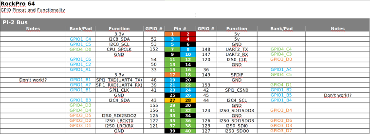
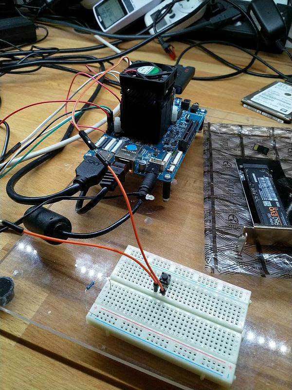
    Was fehlt noch? Der Anschluß der LED. In meinem Beispiel ist die LED wie folgt angeschlossen.

    • Plus(+) der LED an PIN 3 (GPIO1_C4)
    • Minus(-)- der LED an Pin 39 (GND)

    Zum korrekten Anschließen der LED empfehle ich die Lektüre dieses Beitrages!


    Starten des Scriptes

    Um das Script zu starten benutzt man

    sudo python test.py
    

    Ohne sudo bekam ich Fehlermeldungen.


    Fazit

    Es gibt da für mich einige Unbekannte bei dem Thema. Das wären

    • Stimmt die Nummerierung, ist sie komplett?
    • GPIO.setmode(GPIO.ROCK) ermöglichte mir dann mit 52 endlich was zu finden?

    Wir brauchen eine vernünftige Auflistung der Nummern zu den PINs. Gibt es das ? Stimmen alle PIN-Nummern!?

    Bitte dran denken, da kann man sich evt. den ROCKPro64 mit schrotten! Also schön vorsichtig!!

    Danke an Allison und smartdave für die Arbeit!

    Ach, fast vergessen. Ich hab von Python recht wenig Ahnung, macht aber Spaß weil man unkompliziert und schnell zu Ergebnissen kommt.

  • 0_1537460597625_ROCKPro64_GPIO_Reference.png

  • Hiermit kann man seinen ROCKPro64 in Elektroschrott verwandeln! Ich hafte nicht für Schäden! Hirn einschalten vorher! 😉

    Ich bin Euch noch was schuldig geblieben. Nur Ausgänge steuern ist blöd, man braucht auch Eingänge 🙂

    0_1537522069566_Input_ergebnis.jpg

    Beispiel

    Wenn der Taster im Bild betätigt wird, soll die LED blinken.

    Script

    Wir benutzen folgende Ein- Augänge des ROCKPro64.

     # Set Variables
     var_gpio_out = 156
     var_gpio_in = 155
    

    Das heißt:

    • an Pin 1 (3,3V) kommt eine Strippe des Tasters
    • an Pin 29 (Input) kommt eine Strippe des Tasters
    • an Pin 31 (Putput) kommt der Plus-Pol der LED
    • an Pin 39 (GND) kommt der Minus-Pol der LED

    Somit wird auf den Eingang (Pin 29) bei Betätigung des Tasters 3,3 Volt angelegt. Damit wird dann der Eingang als High (1) erkannt. Die LED wird über den Ausgang (Pin 31) gesteuert.

    #!/usr/bin/env python
    
    # Frank Mankel, 2018, LGPLv3 License
    # Rock 64 GPIO Library for Python
    # Thanks Allison! Thanks smartdave!
    
    import R64.GPIO as GPIO
    from time import sleep
    
    print("Output Test R64.GPIO Module...")
    
    # Set Variables
    var_gpio_out = 156
    var_gpio_in = 155
    
    
    # GPIO Setup
    GPIO.setwarnings(True)
    GPIO.setmode(GPIO.ROCK)
    GPIO.setup(var_gpio_out, GPIO.OUT, initial=GPIO.HIGH)       # Set up GPIO as an output, with an initial state of HIGH
    GPIO.setup(var_gpio_in, GPIO.IN, pull_up_down=GPIO.PUD_UP)  # Set up GPIO as an input, pullup enabled
    
    # Test Output
    print("")
    print("Testing GPIO Input/Output:")
    
    
    while True:
            var_gpio_state_in = GPIO.input(var_gpio_in)
            var_gpio_state = GPIO.input(var_gpio_out)                       # Return State of GPIO
            if var_gpio_state == str(0) and var_gpio_state_in == str(1):
                    GPIO.output(var_gpio_out,1)                             # Set GPIO to HIGH
                    print("Input State: " + str(var_gpio_state_in))         # Print results
                    print("Output State IF : " + str(var_gpio_state))       # Print results
            else:
                    GPIO.output(var_gpio_out,0)                             # Set GPIO to LOW
                    print("Input State: " + str(var_gpio_state_in))         # Print results
                    print("Output State ELSE: " + str(var_gpio_state))      # Print results
            sleep(0.5)
    exit()
    
  • Das Projekt (ein Fork) ist aktualisiert und kann jetzt für den ROCK64 und den ROCKPro64 benutzt werden.

    Mit

    setrock('ROCKPRO64')
    

    kann man das Script für den ROCKPro64 anpassen.

    Quelle: https://forum.pine64.org/showthread.php?tid=6419&pid=41270#pid41270

    Sobald ich mal Zeit und Lust habe, werde ich das Testen und hier berichten.

  • Die Coderin von dieser Library Leapo schreibt folgendes

    For anyone using my GPIO library: Just fixed a pretty major bug with GPIO.input, where it would return "1" or "0" as a string rather than as an integer. This fix greatly improves compatibility with scripts written originally for RPI.GPIO. Edit: I've also also fixed Python 3 compatibility (library would crash-out under python 3 if certain debug text was called for).

    Quelle: discordapp.com

    Für den ein oder anderen, der das nutzt vermutlich sehr interessant.

  • Hallo zusammen,

    da ich weiß das dieser Artikel recht beliebt ist, wollen wir den heute mal aktualisieren. Vieles aus den vorherigen Beiträgen passt noch. Es gibt aber kleine Anpassungen.

    Hardware

    • ROCKPro64v21. 2GB RAM

    Software

    • Kamils Release 0.10.9
    • Linux rockpro64 5.6.0-1132-ayufan-g81043e6e109a #ayufan SMP Tue Apr 7 10:07:35 UTC 2020 aarch64 GNU/Linux

    Installation

     apt install python
    

    Danach laden wir das Projekt

    git clone https://github.com/Leapo/Rock64-R64.GPIO
    

    PIN Nummern anpassen

    cd Rock64-R64.GPIO/R64
    nano _GPIO.py
    

    Datei ergänzen

    # Define GPIO arrays
    #ROCK_valid_channels = [27, 32, 33, 34, 35, 36, 37, 38, 64, 65, 67, 68, 69, 76, 79, 80, 81, 82, 83, 84, 85, 86, 87, 88, 89, 96, 97, 98, 100, 101, 102, 103, 104]
    #BOARD_to_ROCK = [0, 0, 0, 89, 0, 88, 0, 0, 64, 0, 65, 0, 67, 0, 0, 100, 101, 0, 102, 97, 0, 98, 103, 96, 104, 0, 76, 68, 69, 0, 0, 0, 38, 32, 0, 33, 37, 34, 36, 0, 35, 0, 0, 81, 82, 87, 83, 0, 0, 80, 79, 85, 84, 27, 86, 0, 0, 0, 0, 0, 0, 89, 88]
    #BCM_to_ROCK = [68, 69, 89, 88, 81, 87, 83, 76, 104, 98, 97, 96, 38, 32, 64, 65, 37, 80, 67, 33, 36, 35, 100, 101, 102, 103, 34, 82]
    ROCK_valid_channels = [52,53,152,54,50,33,48,39,41,43,155,156,125,122,121,148,147,120,36,149,153,42,45,44,124,126,123,127]
    BOARD_to_ROCK = [0,0,0,52,0,53,0,152,148,0,147,54,120,50,0,33,36,0,149,48,0,39,153,41,42,0,45,43,44,155,0,156,124,125,0,122,126,121,123,0,127]
    BCM_to_ROCK = [43,44,52,53,152,155,156,45,42,39,48,41,124,125,148,147,124,54,120,122,123,127,33,36,149,153,121,50] 
    

    Abspeichern.

    Datei test.py anlegen

    nano test.py
    

    Inhalt

    #!/usr/bin/env python
    
    # Frank Mankel, 2018, LGPLv3 License
    # Rock 64 GPIO Library for Python
    # Thanks Allison! Thanks smartdave!
    
    import R64.GPIO as GPIO
    from time import sleep
    
    print("Output Test R64.GPIO Module...")
    
    # Set Variables
    var_gpio_out = 156
    var_gpio_in = 155
    
    
    # GPIO Setup
    GPIO.setwarnings(True)
    GPIO.setmode(GPIO.ROCK)
    GPIO.setup(var_gpio_out, GPIO.OUT, initial=GPIO.HIGH)       # Set up GPIO as an output, with an initial state of HIGH
    GPIO.setup(var_gpio_in, GPIO.IN, pull_up_down=GPIO.PUD_UP)  # Set up GPIO as an input, pullup enabled
    
    # Test Output
    print("")
    print("Testing GPIO Input/Output:")
    
    
    while True:
            var_gpio_state_in = GPIO.input(var_gpio_in)
            var_gpio_state = GPIO.input(var_gpio_out)                       # Return State of GPIO
            if var_gpio_state == 0 and var_gpio_state_in == 1:
                    GPIO.output(var_gpio_out,GPIO.HIGH)                             # Set GPIO to HIGH
                    print("Input State: " + str(var_gpio_state_in))         # Print results
                    print("Output State IF : " + str(var_gpio_state))       # Print results
            else:
                    GPIO.output(var_gpio_out,GPIO.LOW)                             # Set GPIO to LOW
                    print("Input State: " + str(var_gpio_state_in))         # Print results
                    print("Output State ELSE: " + str(var_gpio_state))      # Print results
            sleep(0.5)
    exit()
    

    Beispiel

    Bild Text

    Wenn der Taster im Bild betätigt wird, soll die LED blinken.

    Wir benutzen folgende Ein- Augänge des ROCKPro64.

    # Set Variables
    var_gpio_out = 156
    var_gpio_in = 155
    

    Das heißt:

    • an Pin 1 (3,3V) kommt eine Strippe des Tasters
    • an Pin 29 (Input) kommt eine Strippe des Tasters
    • an Pin 31 (Output) kommt der Plus-Pol der LED
    • an Pin 39 (GND) kommt der Minus-Pol der LED

    Somit wird auf den Eingang (Pin 29) bei Betätigung des Tasters 3,3 Volt angelegt. Damit wird dann der Eingang als High (1) erkannt. Die LED wird über den Ausgang (Pin 31) gesteuert.

    Starten kann man das Script mit

    python test.py
    

  • 0 Stimmen
    3 Beiträge
    392 Aufrufe
    FrankMF

    Gestern mal das Ganze mit einem Cinnamon Desktop ausprobiert. Eine verschlüsselte Installation auf eine PCIe NVMe SSD. So weit lief das alles reibungslos. Der Cinnamon Desktop hat dann leider keine 3D Unterstützung. Sieht so aus, als wenn keine vernünftigen Grafiktreiber genutzt würden. Da ich auf diesem Gebiet aber eine Null bin, lassen wir das mal so. Außerdem mag ich sowieso keine Desktops auf diesen kleinen SBC. Da fehlt mir einfach der Dampf 😉

    Gut, was ist mir so aufgefallen?

    Unbedingt die Daten des Daily Images erneuern, keine alten Images nutzen. Ich hatte da jetzt ein paar Mal Schwierigkeiten mit. Da das ja nun keine Arbeit ist, vorher einfach neu runterladen und Image bauen.

    Warum zum Henker bootet eigentlich. außer meiner Samsung T5, nichts vom USB3 oder USB-C Port?? 👿

  • FTDI Support (ayufan Kernel 5.0)

    Ungelöst Probleme?
    8
    0 Stimmen
    8 Beiträge
    540 Aufrufe
    K

    Hi, leider habe ich bisher keine Antwort von Kamil erhalten. So habe ich selbst mal einen Kernel kompiliert. Als Vorlage habe ich den Ayufan 5.3 rc4 1118 genommen. Also gleiche config nur zusätzlich den FTDI und den CH341 (Arduino clones) Treiber hinzugefügt. Könnt ihr ja mal bei Lust und Laune testen. Für meine Zwecke funktioniert er gut.
    Gruss
    https://drive.google.com/file/d/1kJarihL7bAqN9y6tK-m1V4zHCSEiEWtf/view?usp=sharing

  • Images 0.9.x

    Images
    13
    0 Stimmen
    13 Beiträge
    764 Aufrufe
    FrankMF

    0.9.16: gitlab-ci-linux-build-163 released

    0.9.x 0.9.16: Bump kernel to 4.4.197, 0.9.15: Bump kernel to 4.4.193, 0.9.14: Bump kernel to 4.4.190, 0.9.14: Fix Firefox video playback, 0.9.13: Bump sound volume for Pinebook Pro, 0.9.12: Fix LXDE for Rock64, 0.9.10: Fix support for power/standby LEDs for all boards,
  • Booten von USB3

    Verschoben ROCKPro64
    1
    0 Stimmen
    1 Beiträge
    286 Aufrufe
    Niemand hat geantwortet
  • Booten von der NVMe Platte

    ROCKPro64
    16
    0 Stimmen
    16 Beiträge
    7k Aufrufe
    S

    Für dies Kernal: Linux rockpro64 4.4.167-1213-rockchip-ayufan-g34ae07687fce #1 SMP Tue Jun 18 20:44:49 UTC 2019 aarch64 GNU/Linux

    Booten von der NVMe Platte nicht möglich.

    Ich folgte die folgende Schritte. Leider funktioniert es nicht. Es gibt einen Fehler in Boot.

    Ohne RAID oder LVM config.

    Specs:
    Rockpro64
    Marvel PCIe 88se9230 karte
    SANDISK SSD 120 GB

  • ROCKPro64 - Der Bootvorgang

    Verschoben Hardware
    3
    0 Stimmen
    3 Beiträge
    1k Aufrufe
    FrankMF

    Um einen neuen Kernel booten zu können, brauche ich diese 4 Dateien unter /boot

    config-4.19.0-rc4-1065-ayufan-g72e04c7b3e06 initrd.img-4.19.0-rc4-1065-ayufan-g72e04c7b3e06 System.map-4.19.0-rc4-1065-ayufan-g72e04c7b3e06 vmlinuz-4.19.0-rc4-1065-ayufan-g72e04c7b3e06

    Und den Ordner /boot/dtbs/4.19.0-rc4-1065-ayufan-g72e04c7b3e06 mit folgendem Inhalt

    rock64@rockpro64v2_0:/boot/dtbs/4.19.0-rc4-1065-ayufan-g72e04c7b3e06$ ls -la total 104 drwxr-xr-x 26 root root 4096 Sep 30 09:54 . drwxr-xr-x 6 root root 4096 Sep 30 09:55 .. drwxr-xr-x 2 root root 4096 Sep 30 09:54 al drwxr-xr-x 2 root root 4096 Sep 30 09:54 allwinner drwxr-xr-x 2 root root 4096 Sep 30 09:54 altera drwxr-xr-x 2 root root 4096 Sep 30 09:54 amd drwxr-xr-x 2 root root 4096 Sep 30 09:54 amlogic drwxr-xr-x 2 root root 4096 Sep 30 09:54 apm drwxr-xr-x 2 root root 4096 Sep 30 09:54 arm drwxr-xr-x 4 root root 4096 Sep 30 09:54 broadcom drwxr-xr-x 2 root root 4096 Sep 30 09:54 cavium drwxr-xr-x 2 root root 4096 Sep 30 09:54 exynos drwxr-xr-x 2 root root 4096 Sep 30 09:54 freescale drwxr-xr-x 2 root root 4096 Sep 30 09:54 hisilicon drwxr-xr-x 2 root root 4096 Sep 30 09:54 lg drwxr-xr-x 2 root root 4096 Sep 30 09:54 marvell drwxr-xr-x 2 root root 4096 Sep 30 09:54 mediatek drwxr-xr-x 2 root root 4096 Sep 30 09:54 nvidia drwxr-xr-x 2 root root 4096 Sep 30 09:54 qcom drwxr-xr-x 2 root root 4096 Sep 30 09:54 renesas drwxr-xr-x 2 root root 4096 Sep 30 09:54 rockchip drwxr-xr-x 2 root root 4096 Sep 30 09:54 socionext drwxr-xr-x 2 root root 4096 Sep 30 09:54 sprd drwxr-xr-x 2 root root 4096 Sep 30 09:54 synaptics drwxr-xr-x 2 root root 4096 Sep 30 09:54 xilinx drwxr-xr-x 2 root root 4096 Sep 30 09:54 zte

    Unter /boot/extlinux liegt dann die Datei extlinux.conf

    Die sieht bei mir dann so aus

    timeout 10 menu title select kernel label kernel-4.19.0-rc4-1065-ayufan-g72e04c7b3e06 kernel /boot/vmlinuz-4.19.0-rc4-1065-ayufan-g72e04c7b3e06 initrd /boot/initrd.img-4.19.0-rc4-1065-ayufan-g72e04c7b3e06 devicetreedir /boot/dtbs/4.19.0-rc4-1065-ayufan-g72e04c7b3e06 append rw panic=10 init=/sbin/init coherent_pool=1M ethaddr=${ethaddr} eth1addr=${eth1addr} serial=${serial#} cgroup_enable=cpuset cgroup_memory=1 cgroup_enable=memory swapaccount=1 root=LABEL=TEST rootwait rootfstype=ext4 label kernel-4.19.0-rc4-1065-ayufan-g72e04c7b3e06-memtest kernel /boot/vmlinuz-4.19.0-rc4-1065-ayufan-g72e04c7b3e06 initrd /boot/initrd.img-4.19.0-rc4-1065-ayufan-g72e04c7b3e06 devicetreedir /boot/dtbs/4.19.0-rc4-1065-ayufan-g72e04c7b3e06 append rw panic=10 init=/sbin/init coherent_pool=1M ethaddr=${ethaddr} eth1addr=${eth1addr} serial=${serial#} cgroup_enable=cpuset cgroup_memory=1 cgroup_enable=memory swapaccount=1 root=LABEL=TEST rootwait rootfstype=ext4 memtest

    Darunter kommen dann evt. die alten Kernel die installiert waren, das habe ich hier im Beispiel weg gelassen.

  • stretch-minimal-rockpro64

    Verschoben Linux
    3
    0 Stimmen
    3 Beiträge
    983 Aufrufe
    FrankMF

    Mal ein Test was der Speicher so kann.

    rock64@rockpro64:~/tinymembench$ ./tinymembench tinymembench v0.4.9 (simple benchmark for memory throughput and latency) ========================================================================== == Memory bandwidth tests == == == == Note 1: 1MB = 1000000 bytes == == Note 2: Results for 'copy' tests show how many bytes can be == == copied per second (adding together read and writen == == bytes would have provided twice higher numbers) == == Note 3: 2-pass copy means that we are using a small temporary buffer == == to first fetch data into it, and only then write it to the == == destination (source -> L1 cache, L1 cache -> destination) == == Note 4: If sample standard deviation exceeds 0.1%, it is shown in == == brackets == ========================================================================== C copy backwards : 2812.7 MB/s C copy backwards (32 byte blocks) : 2811.9 MB/s C copy backwards (64 byte blocks) : 2632.8 MB/s C copy : 2667.2 MB/s C copy prefetched (32 bytes step) : 2633.5 MB/s C copy prefetched (64 bytes step) : 2640.8 MB/s C 2-pass copy : 2509.8 MB/s C 2-pass copy prefetched (32 bytes step) : 2431.6 MB/s C 2-pass copy prefetched (64 bytes step) : 2424.1 MB/s C fill : 4887.7 MB/s (0.5%) C fill (shuffle within 16 byte blocks) : 4883.0 MB/s C fill (shuffle within 32 byte blocks) : 4889.3 MB/s C fill (shuffle within 64 byte blocks) : 4889.2 MB/s --- standard memcpy : 2807.3 MB/s standard memset : 4890.4 MB/s (0.3%) --- NEON LDP/STP copy : 2803.7 MB/s NEON LDP/STP copy pldl2strm (32 bytes step) : 2802.1 MB/s NEON LDP/STP copy pldl2strm (64 bytes step) : 2800.7 MB/s NEON LDP/STP copy pldl1keep (32 bytes step) : 2745.5 MB/s NEON LDP/STP copy pldl1keep (64 bytes step) : 2745.8 MB/s NEON LD1/ST1 copy : 2801.9 MB/s NEON STP fill : 4888.9 MB/s (0.3%) NEON STNP fill : 4850.1 MB/s ARM LDP/STP copy : 2803.8 MB/s ARM STP fill : 4893.0 MB/s (0.5%) ARM STNP fill : 4851.7 MB/s ========================================================================== == Framebuffer read tests. == == == == Many ARM devices use a part of the system memory as the framebuffer, == == typically mapped as uncached but with write-combining enabled. == == Writes to such framebuffers are quite fast, but reads are much == == slower and very sensitive to the alignment and the selection of == == CPU instructions which are used for accessing memory. == == == == Many x86 systems allocate the framebuffer in the GPU memory, == == accessible for the CPU via a relatively slow PCI-E bus. Moreover, == == PCI-E is asymmetric and handles reads a lot worse than writes. == == == == If uncached framebuffer reads are reasonably fast (at least 100 MB/s == == or preferably >300 MB/s), then using the shadow framebuffer layer == == is not necessary in Xorg DDX drivers, resulting in a nice overall == == performance improvement. For example, the xf86-video-fbturbo DDX == == uses this trick. == ========================================================================== NEON LDP/STP copy (from framebuffer) : 602.5 MB/s NEON LDP/STP 2-pass copy (from framebuffer) : 551.6 MB/s NEON LD1/ST1 copy (from framebuffer) : 667.1 MB/s NEON LD1/ST1 2-pass copy (from framebuffer) : 605.6 MB/s ARM LDP/STP copy (from framebuffer) : 445.3 MB/s ARM LDP/STP 2-pass copy (from framebuffer) : 428.8 MB/s ========================================================================== == Memory latency test == == == == Average time is measured for random memory accesses in the buffers == == of different sizes. The larger is the buffer, the more significant == == are relative contributions of TLB, L1/L2 cache misses and SDRAM == == accesses. For extremely large buffer sizes we are expecting to see == == page table walk with several requests to SDRAM for almost every == == memory access (though 64MiB is not nearly large enough to experience == == this effect to its fullest). == == == == Note 1: All the numbers are representing extra time, which needs to == == be added to L1 cache latency. The cycle timings for L1 cache == == latency can be usually found in the processor documentation. == == Note 2: Dual random read means that we are simultaneously performing == == two independent memory accesses at a time. In the case if == == the memory subsystem can't handle multiple outstanding == == requests, dual random read has the same timings as two == == single reads performed one after another. == ========================================================================== block size : single random read / dual random read 1024 : 0.0 ns / 0.0 ns 2048 : 0.0 ns / 0.0 ns 4096 : 0.0 ns / 0.0 ns 8192 : 0.0 ns / 0.0 ns 16384 : 0.0 ns / 0.0 ns 32768 : 0.0 ns / 0.0 ns 65536 : 4.5 ns / 7.2 ns 131072 : 6.8 ns / 9.7 ns 262144 : 9.8 ns / 12.8 ns 524288 : 11.4 ns / 14.7 ns 1048576 : 16.0 ns / 22.6 ns 2097152 : 114.0 ns / 175.3 ns 4194304 : 161.7 ns / 219.9 ns 8388608 : 190.7 ns / 241.5 ns 16777216 : 205.3 ns / 250.5 ns 33554432 : 212.9 ns / 255.5 ns 67108864 : 222.3 ns / 271.1 ns
  • Erste Lebenszeichen

    ROCKPro64
    1
    0 Stimmen
    1 Beiträge
    494 Aufrufe
    Niemand hat geantwortet